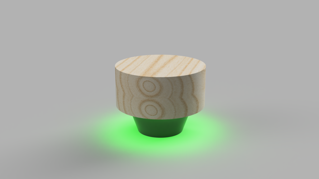
Toroidal propellers experiments

The whole world heard about toroidal propellers when MIT published its studies (February 2023). While some similar concepts were developed earlier and they were not the only ones working on this problem they definitely got plenty of attention. People on YouTube have been testing it in various scenarios ranging from drones to PC fans. This post tries to present a different attempt and hopefully will be developed in the future to show some of the experiments performed by Nikodem Bartnik on the topic of toroidal propellers.

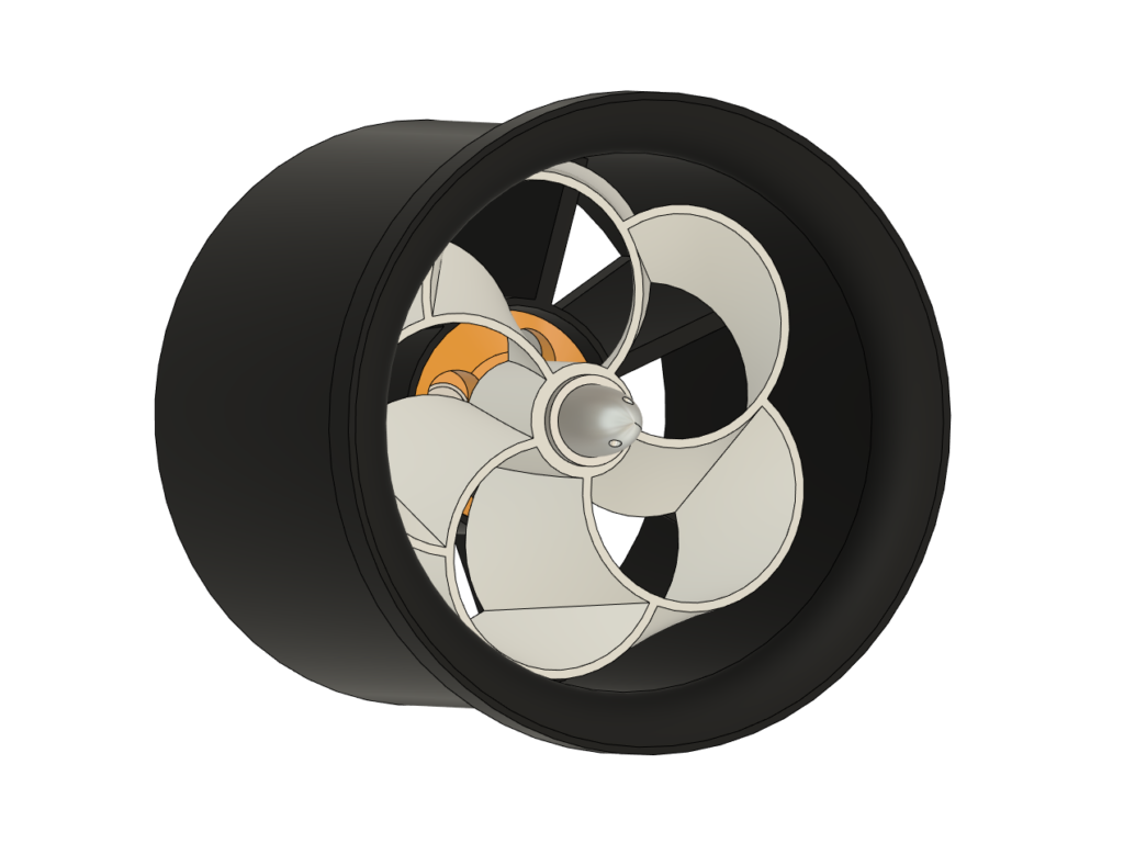
The idea for an experiment was first born when the concept of toroidal EDF happened to stumble across my mind. The results of the tests can be found below:

An important question should be asked, does it make any sense to make a toroidal EDF? I don’t think so. Because of how an EDF works it will not benefit a lot from a toroidal propeller. Nonetheless, I wanted to try, experiment and measure some data in order to see it on my own.

Check out my products and support my work!

The results of the fan performance regarding thrust and max wind speed can be observed on the plots below.

All the files used to print this EDF with different versions of the propeller can be found here:

https://www.thingiverse.com/thing:6111321

Parts list

The parts list for this project is rather short as you only need a motor, ESC, and an RC remote. The rest of the parts are 3D printed.

NameAmountlink
A2212 motor1https://amzn.to/3POZw0n
ESC1https://amzn.to/3rpmZes
RC remote1https://amzn.to/3O5Mp9H

if you want to perform some experiments like I did a thrust stand might be useful. I build one 5 years ago, here you can find detailed instructions on how to do it:

https://www.instructables.com/Brushless-Motor-Thrust-Stand/

This post is a work in progress and will be developed in the future. I am working on converting a $15 cooling fan to a toroidal one and will share the results of this experiment here.

Screw Counting Machine

Since I started offering the parts to build an IndyMill I have been looking at various ways to optimize the process of preparing, packing, and branding. I think some of the things I am doing might be interesting for some of you as I am always trying to find the most DIY, easy and eco-friendly solutions. I will share more details about different methods and projects I created at Indystry.cc but in this project, I would like to focus on the most time-consuming problem – counting the screws.

To illustrate how big of a problem that was let me tell you more about the set of screws for IndyMill. There are 13 different types of screws and nuts, in total 255 screws. So far every single screw had to be manually counted. I took great care when packing the screws and usually double-counted everything to make sure that each set was perfect.

There are also bearings in the kit, only 10 of them so that’s easy to count. It takes about 8 hours to create 20 sets with all the components, considering I am not selling the parts at a huge volume it wasn’t a big problem but still there is plenty of room for improvement. The goal for this project was easy – building a machine that is able to easily, quickly, and accurately count screws.

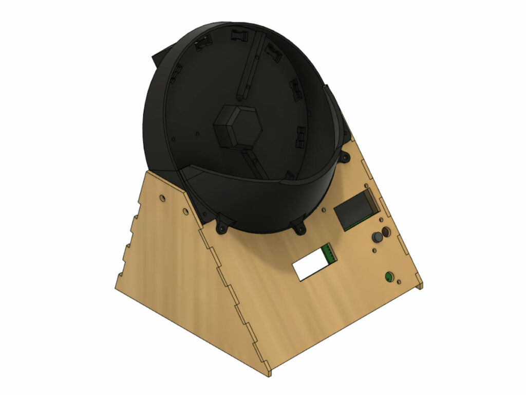
While the goal was pretty well defined getting all 3 subgoals at once is not easy at all and most likely will take at least a few iterations. For that reason from the beginning, I decided to treat this project as a prototype that lets me verify the idea and its feasibility. To test the idea and build a prototype we usually don’t need a lot and for that reason, I used cheap components, 3D printed parts, and thin plywood.

Design

Design

Parts and files

You can find all the files required to build this project on my GitHub:

OpenScrewCounter
GitHub repository for open-source machine for precise and reliable screw counting. Designed with 3D printed and laser cut parts as well as Pi Pico based electronics.

And here is a list of parts I used for this project with links to some of them. Keep in mind that as I mentioned this is a prototype of a new machine I would like to build in the future. There are a lot of things that could be upgraded to make the machine more reliable and in general better.

NameAmountLink
Raspberry Pi Pico1https://amzn.to/3FnSxVT
DC motor1https://amzn.to/405kJVr
7 segment display1https://bit.ly/40bwYQB
Buttons3https://amzn.to/3yK9nul
6804 Bearing1https://amzn.to/40ppZDR
Some screwsa lothttps://amzn.to/3leCWBm

This is not a complete list of parts as there are a lot of small electronic components and also most likely you will have to adapt the project to your needs.

Manufacturing

There are some 3D-printed parts you have to print on your own. It really doesn’t matter that much whether you use PLA or PETG, any material will do. Personally, I used PLA for this project. There are also plywood parts that I cut with a CO2 laser. Those parts can be easily replaced with 3D printed parts in case you don’t have an access to a laser cutter. Another alternative is to machine them with a CNC machine.

For printing, I used my slightly modified Ender3 printer. When I think about it now, this printer is already 4 years old and the only thing I replaced is the motherboard (I wanted to have silent TMC drivers, the original was perfectly fine and there was no reason to replace it), build plate (I broke the original one and adhesion on this golden powder plate is better) and plenty of nozzles. Everything else is as it originally was on the ender.

As a laser, I used my Epilog Zing 16. It is a really cool, professional and unfortunately pricey laser cutter. This cutter is a prize I won during one of the contests organized by Instructables, you should check them out! A cheaper alternative that require some upgrades out of the box to turn it into a usable and capable laser is a K40 laser like this one.

All the files are in the GitHub repository linked above.

Assembly

Assembly is so straightforward that I am not going to explain it in detail there. You need some M3 and M5 screws, wood glue might be useful to join plywood parts. In my video you can see some clips from the assembly but keep in mind I assembled the machine at 5 different stages of the design there and the final one differs a bit.

Problems

Instead of listing the problems let’s focus on the solutions:

  • Bigger drum – this is the element that holds the screws. It’s not big enough to hold a lot of screws. For my use case, it’s just a bit slow but I could easily use it as it is. But because I always want my projects to be appealing to a large audience I know a bigger drum may be beneficial.
  • Better motor with an encoder – I used a very cheap motor, like a very very cheap motor, you can buy it for about a dollar. The next version should incorporate a more powerful motor capable of turning at slower and higher speeds depending on the need. Additionally, an encoder shall be used to allow for stall detection.
  • More accurate laser sensor – using an LED and a photoresist is a decent solution but not accurate enough. Implementing two of these sensors to really make sure that the screws are properly counted is also to be considered.
  • Bigger display with button/encoder – to control all the settings
  • External communication interface – SPI, I2C or CAN to integrate the machine with other machines. For example a rotary table with containers of screws to allow for continuous counting.

I am pretty sure there is a lot more to upgrade, if you have any ideas and want to share them, feel free to send me an email.

Electronics, breadboard, CNC machining a PCB

Starting with a breadboard prototype where modifying anything is really easy is always a good idea. So I started by connecting Pi Pico with 7 segment display to check if everything work as intended. The simple circuit assembled on the breadboard is presented in the image below.

And after that, I moved to KiCAD to design the schematic and PCB layout. My plan was to make the PCB on my own with a modified CNC machine that I made just for PCB machining. And the result of that process you can see on the image above as well as in the video. PCB files are available in the GitHub repository as well.

Programming

Pi Pico or RP2040 can be programmed in Python and since I tried using this microcontroller I completely fell in love with it. Python is definitely my favorite programming language and as I am studying data science now for my master’s degree I am using it quite often for university projects.

The fun part while programming was using ChatGPT to write a function for controlling the 7-segment display. It wasn’t perfect it wasn’t working straight from the chat but the errors were easy to spot and fix. So definitely using this cool AI technology saved me some time for this project.

Other than that firmware for the project is rather simple. You can upload it to the pico with Thonny a simple IDE.

Final thoughts

Honestly, unfortunately, it’s not yet “production ready” I am not going to use it to pack the screws as I can’t trust it. The counting process is not reliable enough. I can use it as a machine that assists me during counting but to be 100% sure I have to count it manually too. So what’s next? Second better, bigger and more expensive version. Not a prototype but a production-ready unit. Follow my YouTube channel and Instagram to be notified when the project is ready, you can also support my work on Patreon:

DIY Solar Powered Garden Watering System

Automating every day tasks are the best projects for so many reasons. You can find a real problem and take it as a challenge to automate it. In the end you will end up with plenty of new knowledge, practical experience with problem solving and more time for new projects because a new project will take care of the every day task. Simple and really rewarding project of this kind is an automated watering system add to that solar power and you have a perfect solution!

To learn more about the project, how I built it, problems I faced and how it works take a look at this video:

Parts

Here is a list of parts you will need to build a Pico watering system. You cna find all the files for both systems on my GitHub, links at the end of this page.

NameAmazonAliexpress
Raspberry Pi Picohttps://amzn.to/3O2GBdGhttps://bit.ly/3c9K7FP
Solar panel and chargerhttps://amzn.to/3PqgpLphttps://bit.ly/3yDzbIe
Garden irrigation systemhttps://amzn.to/3uLS3DLhttps://bit.ly/3c9sE0m
Pumphttps://amzn.to/3O74vF0https://bit.ly/3z0th5v
Water level sensorhttps://amzn.to/3z16nL9https://bit.ly/3nVWZSD
IRFZ44Nhttps://amzn.to/3O1NyvJhttps://bit.ly/3aG8udU
LEDshttps://amzn.to/3yxl1Zjhttps://bit.ly/3NZ0nXz
Buttonshttps://amzn.to/3z0r75Thttps://bit.ly/3yD8UtK
Batteryhttps://amzn.to/3ceAIx6

Links above are affiliate so by using them you support my work at no extra cost. If you would like to support me in a different way you can check out my store or my Patreon:

Become a Patron!

Two systems

My plan was to build a watering system with a few sensors just for fun. While building it I started adding more and more sensors and ended up with a pretty sophisticated system. Also I wanted to make this project in a good old DIY fashion to make it easy for everyone to replicate. In the end I wasn’t quite happy with the system as it was too complicated, there was too many cables everywhere and it wasn’t simple enough to be elegant.

Ad

It’s important to mention that this first system was working great for 11 days and was perfectly watering my garden. Unfortunately the power consumption was pretty high because of many LEDs I had there so it would only work for a few more cloudy days before running out of battery. My DIY soil moisture sensors weren’t working reliably and after creating the plots all the sensors weren’t really needed anymore. All I needed was a simple watering system.

My DIY soil moisture sensor

It obviously wasn’t a waste of time because I learned a lot while making this first version of the system and I used that experience while making the second one. Also with the data collected over 11 days I made some cool looking plots. There is a vertical line every 86 milion milliseconds (that’s 24 hours) so we can see that we have data from almost full 11 days. It was collected during a heatwave in Poland (that was quite fortunate because the system was able to charge fully during the day to survive the night).

Ground and air temperature plots over 11 days of the test

Here we can see sudden drops in the data from ground moisture sensors, unfortunately it is caused by a voltage drop on the battery when turning on the pump. Based on these plots we can conclude that these sensors weren’t working properly. I hope to try to build my own capacitive moisture sensor soon.

Ground moisture data from DIY resistive sensors that unfortunately weren’t working properly
Sunlight data

Here we can see nice correlation between the plots above and below. It’s also visible that the solar charging system wasn’t big enough and wasn’t able to charge the battery on a cloudy day and it got discharged significantly. That’s why reducing power consumption in such systems is really important.

Voltage on a battery

For that reason I decided to start all over again and design a new simple system with only necessary components that consumes less current, is easier to build and more elegant. This time instead of using Arduino (Arduino is great and I still love it but sometimes it’s nice to experiment and try something new) I used Raspberry Pi Pico a microcontroller based board from Raspberry Pi based on RP2040 chip. It’s incredibly chip for what it can offer and is programmed in Python. It’s not the best choice for extreme low power solutions but I am using here a 12V 4Ah battery with a 10W solar panel so that’s not the most important factor for me. RP2040 chip itself is low cost compared to other solutions and what’s really important these days (July 2022) is available. Adding to that a 7805 voltage regulator, IRFZ44N MOSFETs, buttons and a few LEDs I designed a simple single sided PCB – single sided means easy to make at home. To make it I used a $200 CNC machine.

Machining a PCB on a $200 CNC machine with a really nice result
Ad
Final PCB for Pico watering system

There is two of everything on the PCB so you can run two separate systems for different parts of the garden (it’s not yet implemented in the program). With two buttons and 8 LEDs you can easily set number of watering cycles per day (between 1 and 4) and watering cycle time (you can choose from 2, 4, 6 and 8 minutes per cycle) of course that can be also adjusted in the program depending on what you need in your garden. Settign are stored in the flash memory of the Pico, it’s amazing that you can simply safe a file there as you would in a normal Python running on your computer!

Simple LED and buttons make can make a great user interface

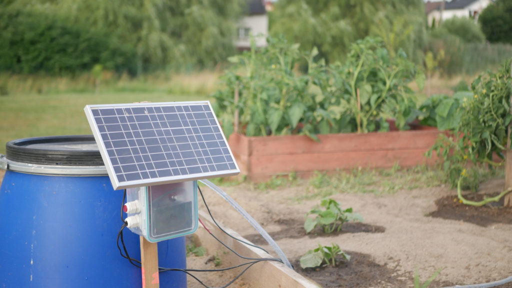
Case was 3D printed with PETG on Ender3 and additionally closed in a 2l food container together with the battery to protect it. I also used cable gland to go with the cables through the container. In the end everything was attached to a a wooden pole and solar panel got pointed south for maximum efficiency. I used a 150l water reservoir that honestly after testing it for two weeks is a bit small and something closer to 300l would be great. Also a rain water collection system could help here significantly.

Files

You can find all the files for this project on my GitHub:

Here is a link to the Pico watering system:
https://github.com/NikodemBartnik/Pico-Watering-System

And here is a link to the WDCS (Watering and Data Collection System):
https://github.com/NikodemBartnik/WDCS

Feel free to ask any questions, share the video and contribute to the open source project!

Happy making and have a nice day!

Arduino Based Air Quality Monitor

The air quality is a pretty big problem in my city. We have a monitoring station but it’s quite far from where I live so I decided to build myself a local, simple and nice-looking air quality monitor. You can learn more about the whole project and how I made it in this video:

Below you can find all the files and code for the project. And here are the parts that I used:

PartLink
Arduino Nanohttps://bit.ly/32xGF06
Air Quality Sensorhttps://bit.ly/36jWXLj
NeoPixel Ringhttps://bit.ly/3lhRM4O

Code

#include <Adafruit_NeoPixel.h>
#include <SoftwareSerial.h>

#define LED_PIN 6 
#define SLEEP_PIN 5
#define MAX_PM1_LEVEL 50
#define MAX_PM25_LEVEL 30
#define MAX_PM10_LEVEL 40
#define NUMPIXELS 24 
Adafruit_NeoPixel pixels(NUMPIXELS, LED_PIN, NEO_GRB + NEO_KHZ800);

// 0 - green, 1 - blue, 2- orange, 3 - red
int last_color = 5;

#define LENG 31   //0x42 + 31 bytes equal to 32 bytes
unsigned char buf[LENG];

SoftwareSerial SoftSerial(10, 11); // RX, TX


void setup() {
  SoftSerial.begin(9600);
  Serial.begin(9600);
  pixels.begin(); 
  pinMode(5, OUTPUT);
}

void loop() {

digitalWrite(SLEEP_PIN, HIGH);
delay(1000L * 60L);
int pm01_level = 0;
int pm25_level = 0;
int pm10_level = 0;

int air_quality[3];

CheckAirQuality(air_quality);

pm01_level = air_quality[0];
pm25_level = air_quality[1];
pm10_level = air_quality[2];


if(pm01_level < MAX_PM1_LEVEL && pm25_level < MAX_PM25_LEVEL && pm10_level < MAX_PM10_LEVEL){
  if(last_color != 0){
  SetColor(0,30,0);
  }
  last_color = 0;
}else if((pm01_level > MAX_PM1_LEVEL && pm25_level < MAX_PM25_LEVEL && pm10_level < MAX_PM10_LEVEL) || (pm01_level < MAX_PM1_LEVEL && pm25_level > MAX_PM25_LEVEL && pm10_level < MAX_PM10_LEVEL) || (pm01_level < MAX_PM1_LEVEL && pm25_level < MAX_PM25_LEVEL && pm10_level > MAX_PM10_LEVEL)){
  if(last_color != 1){
  SetColor(0,0,30);
  }
  last_color = 1;
}else if((pm01_level > MAX_PM1_LEVEL && pm25_level > MAX_PM25_LEVEL && pm10_level < MAX_PM10_LEVEL) || (pm01_level > MAX_PM1_LEVEL && pm25_level < MAX_PM25_LEVEL && pm10_level > MAX_PM10_LEVEL) || (pm01_level < MAX_PM1_LEVEL && pm25_level > MAX_PM25_LEVEL && pm10_level > MAX_PM10_LEVEL)){
  if(last_color != 2){
  SetColor(30,10,0);
  }
  last_color = 2;
}else if(pm01_level > MAX_PM1_LEVEL && pm25_level > MAX_PM25_LEVEL && pm10_level > MAX_PM10_LEVEL){
  if(last_color != 3){
  SetColor(30,0,0);
  }
  last_color = 3;
}
Serial.print("PM01: ");
Serial.println(pm01_level);
Serial.print("PM2.5: ");
Serial.println(pm25_level);
Serial.print("PM10: ");
Serial.println(pm10_level);

digitalWrite(SLEEP_PIN, LOW);
delay(1000L * 60L * 3L);

}


void SetColor(int r, int g, int b){
  
  for(int a = 255; a > 0; a--){
    pixels.setBrightness(a);
    pixels.show();
    delay(20);
  }
pixels.clear();
pixels.setBrightness(255);
pixels.show();
  for(int i = 0; i < NUMPIXELS; i++) { 
    pixels.setPixelColor(i, pixels.Color(r, g, b)); 
    pixels.show();   
    delay(50); 
  }


}

void CheckAirQuality(int* air_quality){
  if(SoftSerial.find(0x42)){    //start to read when detect 0x42
    SoftSerial.readBytes(buf,LENG);

    if(buf[0] == 0x4d){
      if(checkValue(buf,LENG)){
        air_quality[0] = transmitPM01(buf); //count PM1.0 value of the air detector module
        air_quality[1] = transmitPM2_5(buf);//count PM2.5 value of the air detector module
        air_quality[2] = transmitPM10(buf); //count PM10 value of the air detector module
      }
    }
  }
}


char checkValue(unsigned char *thebuf, char leng)
{
  char receiveflag=0;
  int receiveSum=0;

  for(int i=0; i<(leng-2); i++){
  receiveSum=receiveSum+thebuf[i];
  }
  receiveSum=receiveSum + 0x42;

  if(receiveSum == ((thebuf[leng-2]<<8)+thebuf[leng-1]))  //check the serial data
  {
    receiveSum = 0;
    receiveflag = 1;
  }
  return receiveflag;
}

int transmitPM01(unsigned char *thebuf)
{
  int PM01Val;
  PM01Val=((thebuf[3]<<8) + thebuf[4]); //count PM1.0 value of the air detector module
  return PM01Val;
}

//transmit PM Value to PC
int transmitPM2_5(unsigned char *thebuf)
{
  int PM2_5Val;
  PM2_5Val=((thebuf[5]<<8) + thebuf[6]);//count PM2.5 value of the air detector module
  return PM2_5Val;
  }

//transmit PM Value to PC
int transmitPM10(unsigned char *thebuf)
{
  int PM10Val;
  PM10Val=((thebuf[7]<<8) + thebuf[8]); //count PM10 value of the air detector module
  return PM10Val;
}

It’s hard to create a nice schematic for this project as there is no Fritzing library for PM2.5 sensor, and I have no idea how to create one 🙂 That’s why below you can find a text only explanation on connection, definitely not a perfect option but at the same time better than nothing:

DevicesArduino
Air Sensor RXPIN 10
Air Sensor TXPIN 11
Air Sensor 5V5V
Air Sensor GNDGND
Air Sensor SLEEPPIN 5
LED Ring DIPIN 6
LED Ring 5V3.3V
LED Ring GNDGND

As you can see in the table above I connected LED ring 5V to the 3.3V on the Arduino, that’s because there is only one 5V pin on Arduino Nano and it has to be used for Air quality sensor because it doesn’t work with 3.3V.

Thanks a lot for reading and happy making! I hope my air quality sensor will serve you well! And don’t forget to check out my other projects:

Object Tracking Robot – FollowBot V2

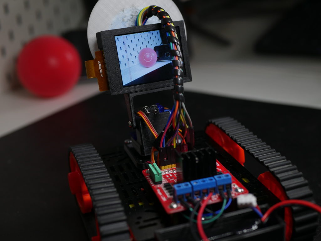
This is a second version of original FollowBot made in 2015. This one uses Maix Sipeed board with a camera and LCD screen. With 2 micro servo motors I made a small pan-tilt mechanism. Here you can read some more about how I made this project.

I decided to use new Maix Sipeed board, it’s quite powerful, has build in camera and you can program that in python so I though it should be quite easy to make such project with this board. I was right. If you have at least a little bit of experience with Python and electronics you can do some really cool stuff.

Firstly I had to develop a simple program for tracking red objects. I started by using blob detection algorithm. Basically it searches for all red blobs on the image and store that in a table. Then I had to find the biggest blob as that’s most likely what I want to track (simple for loop with one if statement and one variable can do it). And that’s it, within 40 lines of code you can detect simple single color objects. You can read more about that and find some examples here:

https://maixpy.sipeed.com/en/libs/machine_vision/image.html

https://github.com/sipeed/MaixPy_scripts

Parts

PartLink
Maix Sipeedhttps://bit.ly/31BwNCA
Robot Chassishttps://bit.ly/31zBVXK
Motor Driverhttps://bit.ly/31yPs1V
Servohttps://bit.ly/2EqHQ96
Batteryhttps://bit.ly/3jrPVJr
[mailerlite_form form_id=2]

There is no servo library for this board so that’s a downside because you need to figure out on your own how to control a servo (later I noticed that there is a servo example on github linked above). Servo is controlled with 50Hz PWM signal, high signal should be between 1 ms – 2 ms so that’s a duty of 5-10% (5% * 1/50s = 1 ms, 10%*1/50s = 2 ms). With a timer I was able to set up such PWM signal, a simple servo example can be found in all of the files (you can download them at the bottom of the page).

I also designed my own minimal pan and tilt mechanism in Fusion360. STL files are also at the bottom of this page.

I made my own functions to control DC motor driver but that was obviously very easy. Here is how I connected the motor driver and servos to the board.

Connection

Maix SipeedDC Motor Driver/Servo
PIN 0Pan Servo Signal
PIN 1Tilt Servo Signal
PIN 9Motor Driver ENA
PIN 10Motor Driver IN1
PIN 11Motor Driver IN2
PIN 12Motor Driver IN3
PIN 13Motor Driver IN4
PIN 14Motor Driver ENB
GNDMotor Driver and Servo GND
5VMotor Driver and Servo 5V

After that I simply connected all small programs that I wrote and put everything on my robot chassis. And it was time for the final test that you can see on the video below.

Here you can find a ZIP archive with all the files including my small subprograms, main followbot.py and all STL files that you can print. Feel free to edit those and customize this project to make it work for you. Don’t forget to share your work with others and link to my project 🙂

Thanks for reading this short project description, it’s definitely not a full tutorial but I hope it will be helpful for some of you!