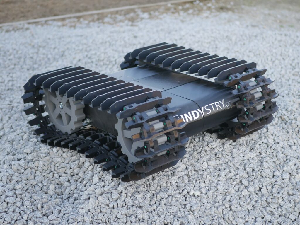
Big 3D printed robot platform on tracks
While working with GPS RTK and setting up my own RTK base station I thought it would be cool to […]
Big 3D printed robot platform on tracks Read Post »
While working with GPS RTK and setting up my own RTK base station I thought it would be cool to […]
Big 3D printed robot platform on tracks Read Post »
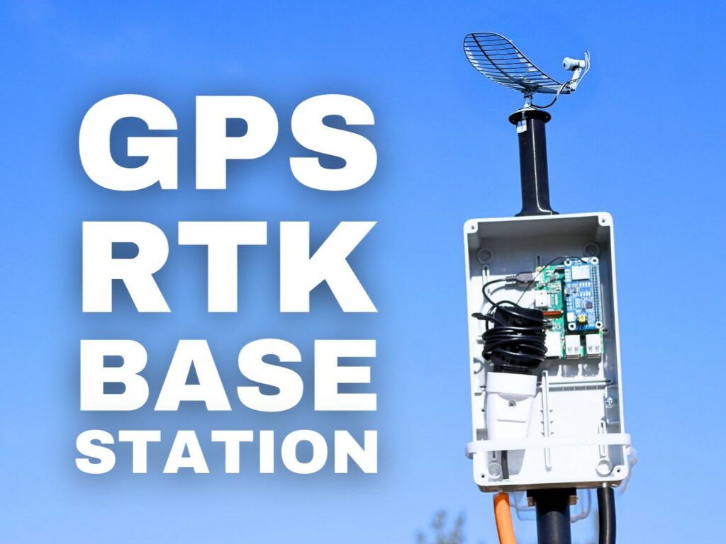
RTK is a cool technology but it’s also very expensive. As always with time as the adoption of the technology is growing the prices go lower and lower. The same happened with GPS RTK, these days (in 2025) you can buy LC29H from WasveShare for just $60…
How to use LC29H – the cheapest GPS RTK module Read Post »
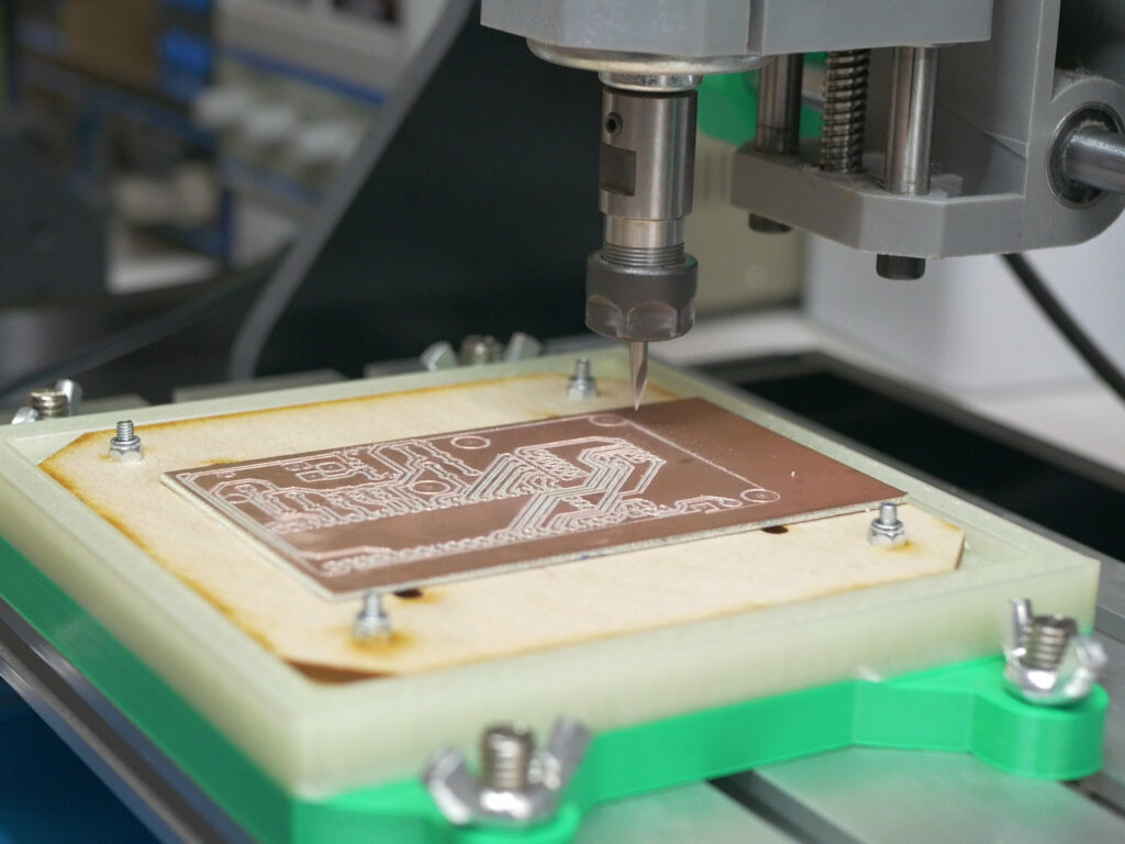
If you would like to add auto level (also called height map) feature to CNCjs this post is for you. It’s not as easy and straightforward as I wish it to be but with this tutorial you will easily set it up and use it without remembering complicated terminal commands.
How to use auto level in CNCjs Read Post »
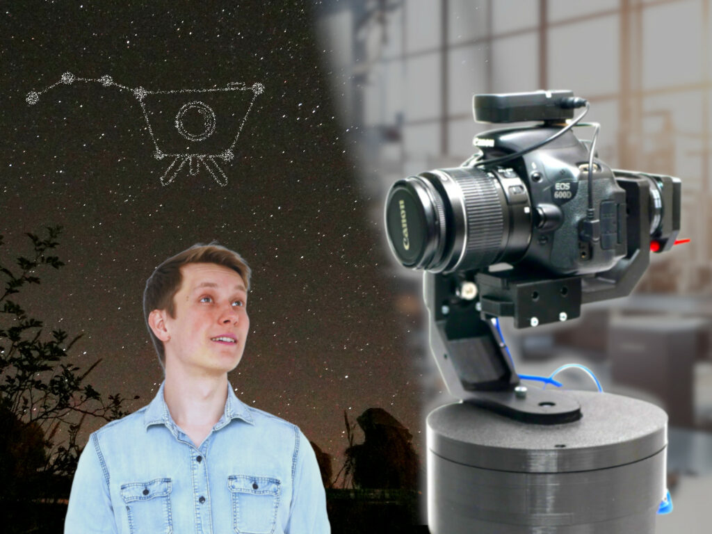
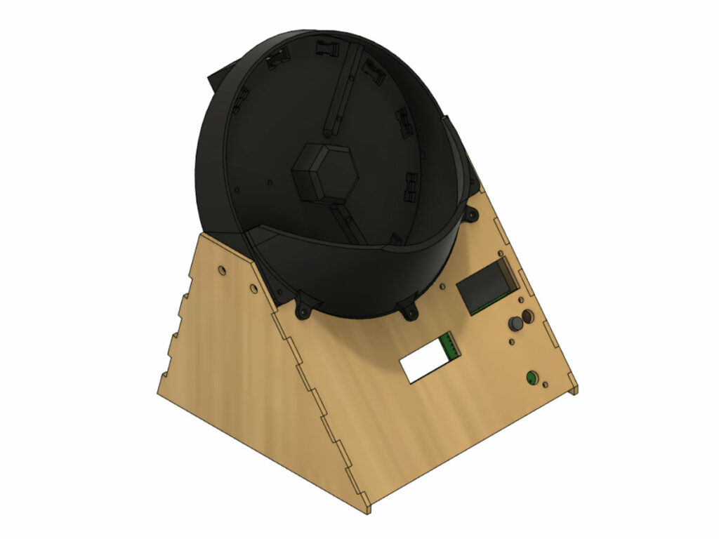
I have been always very fascinated with space. The easiest and 100% safe way to almost “touch” the space from
3 axis star tracking system for astrophotography – StarTrckr Read Post »
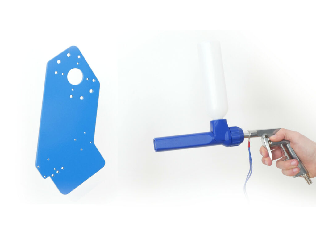
This will be a brief introduction to DIY powder coating. I would like to present you all the tools you
How to: DIY powder coating Read Post »
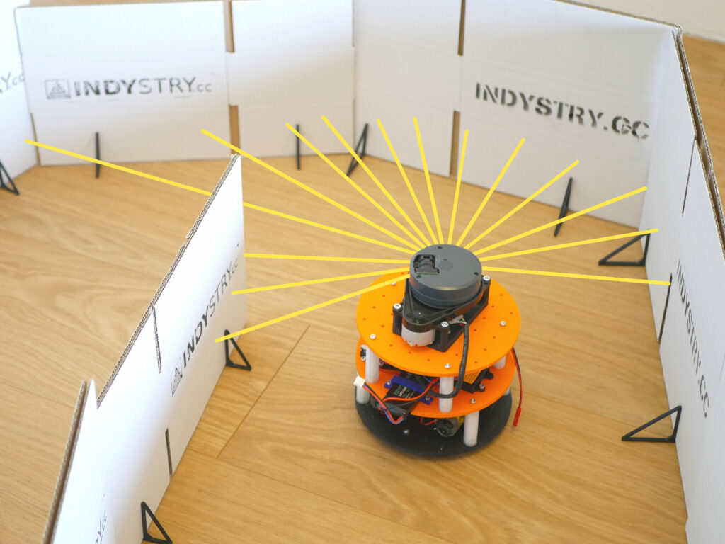
The first video (the one above) was quite successful and the feedback was very positive so I made another one
Machine Learning Robot Driving Autonomously with Arduino and LIDAR Read Post »
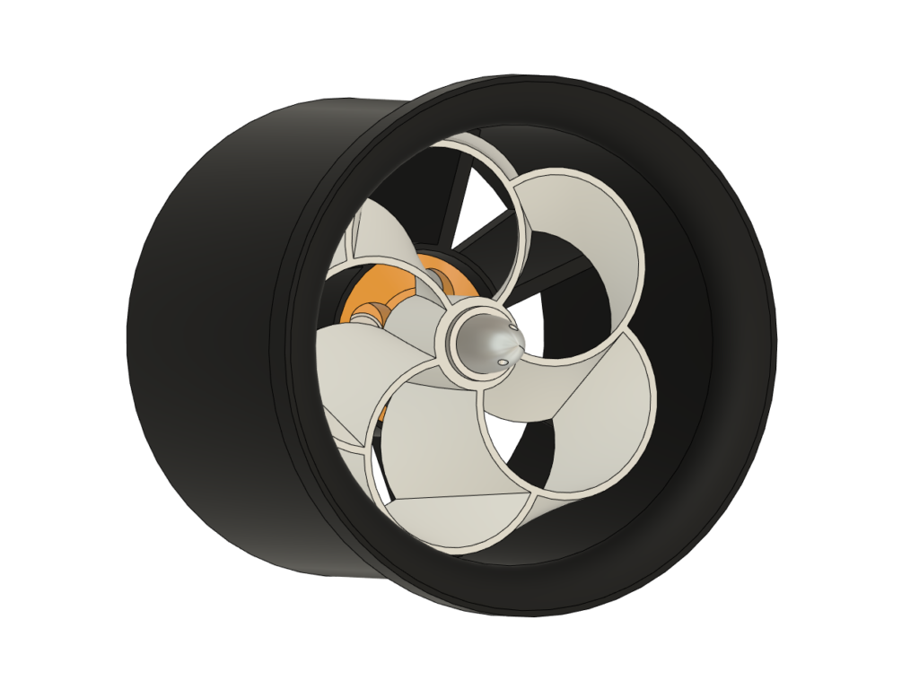
The whole world heard about toroidal propellers when MIT published its studies (February 2023). While some similar concepts were developed
Toroidal propellers experiments Read Post »
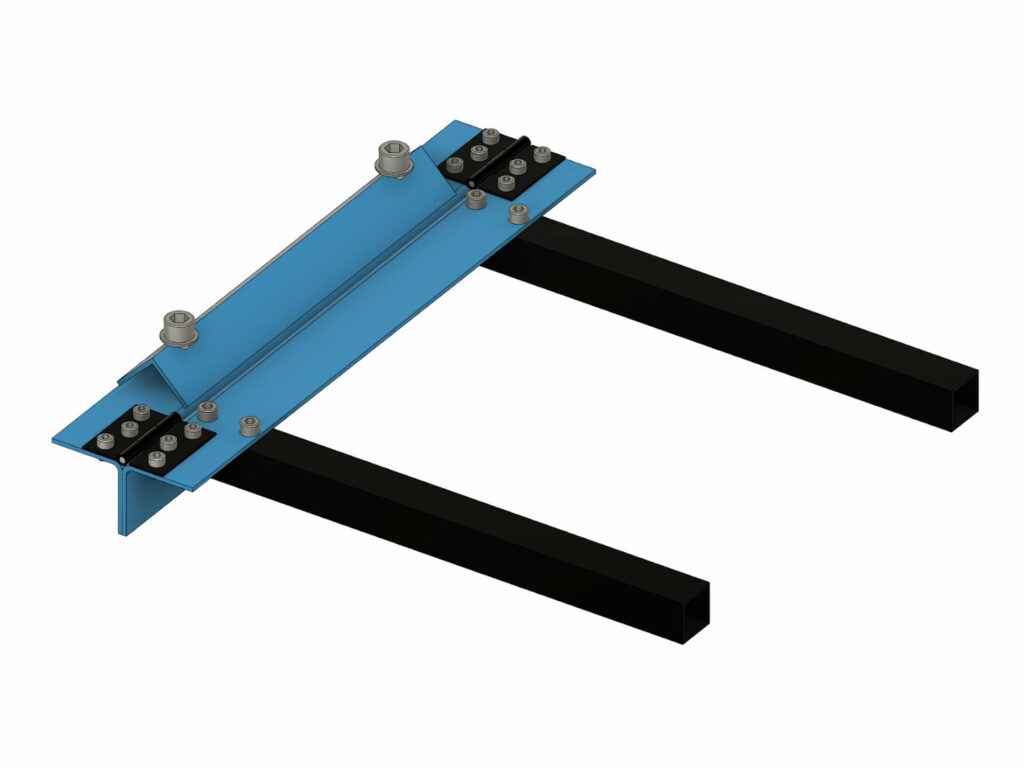
Simple metal bending tool that you can build with a drill and an angle grinder, no welding required! When building
DIY Mini Metal Brake Read Post »
Since I started offering the parts to build an IndyMill I have been looking at various ways to optimize the
Screw Counting Machine Read Post »
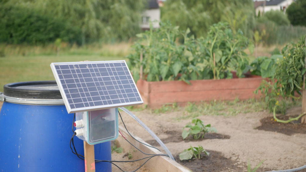
Automating every day tasks are the best projects for so many reasons. You can find a real problem and take
DIY Solar Powered Garden Watering System Read Post »
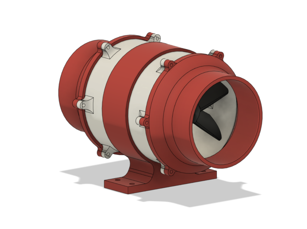
This is a 3D printed duct fan that can be used with a 775 motor or a popular BLDC (for
3D Printed duct fan Read Post »
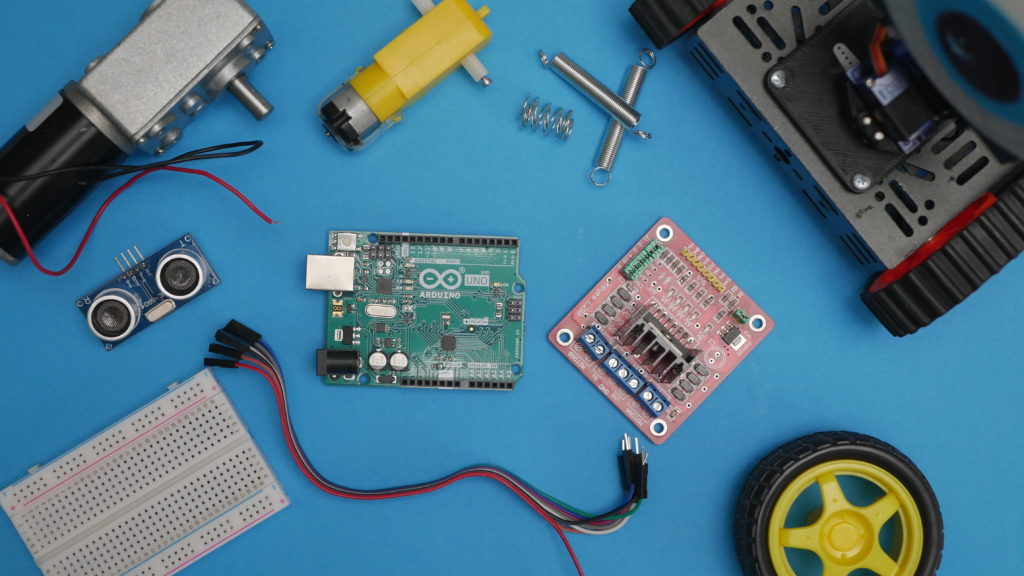
Robots are cool, I think we all agree on that. Right here I would like to give you a short
How to build a robot? Read Post »