How to use auto level in CNCjs

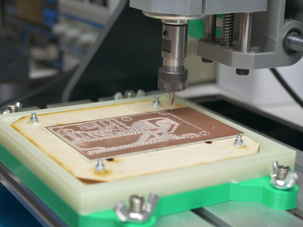
I love CNCjs for the interface and ease of use. But it lacks autolevel or height map feature which is essential to make PCBs with your CNC machine. I tried other CNC controllers that have that feature built in but very often they are just unusable for the interface or performance. After a quick search I found a GitHub repository with code that was meant to implement auto-level in CNCjs. I was able to easily get it working on my Windows computer, it was a long time ago and I managed to forget how to do it but now I need it to work on my laptop with macOS. It turned out to be way harder than I thought but I managed to find a way to get it working. I will show you all the steps and how I automated running the software so that it will be easier for you but also or me in case I uninstall it again and forget how to set it up. Let’s start!

Install CNCjs

Obviously, you will need CNCjs, if you don’t have it yet, you can install it from here: https://cnc.js.org

You can go and install it on Raspberry Pi but I prefer to use it as a desktop app on my computer. It’s quite easy to install if you scroll a bit on the main page you can find links to install it on macOS, Windows, and Linux.

Autolevel software

Thanks to the power of GitHub and open source there is code that was created to get autolevel to work in CNCjs, you can find it here: https://github.com/kreso-t/cncjs-kt-ext

Unfortunately, it’s not a simple plugin or a widget that you can add. It also has not been added to the main CNCjs app. So until then, we need to install it manually. I would love to write such a plugin based on it on my own but I honestly don’t know how to do that. I would love to learn, but right now there are other tasks with higher priority.

If you are not familiar with GitHub just go to the page and click the green code button. A menu will extend under the button, you can click download zip. Once the download is finished you can extract the zip file on your drive in some known location.

It’s time to open the terminal. Here we just need to navigate to the folder that we just extracted in my case it’s in

/Users/nikodembartnik/CNCjs_autolevel/cncjs-kt-ext-master

If you are not familiar with the terminal on your computer you need to use the cd command. If you want to see the content of the folder you can use ls command. Here is how I did it:

once you are in the folder type: npm install and hit enter.

Now in order to turn it on, it’s quite tricky as you need to run it with a proper command every time and make sure that the correct serial port and app port are selected. To make it even more complicated the port where CNCjs is running is random and different every time you turn CNCjs on. Therefore I decide to do it in an easier way using the Automator app on Mac.

I wrote a bit longer commands to run CNCjs with a specific port then wait 10 seconds and ran the auto-level extension by connecting for a specific user, internet port, and USB port. You will also need to create a user in CNCjs and copy your ID and SECRET keys into the command.

To run CNCjs:

open -a CNCjs --args -- --port 8000

Wait 10 seconds and then:

cd /Users/nikodembartnik/CNCjs_autolevel/cncjs-kt-ext-master &&
/usr/local/bin/node . --id 'ID_HERE' --name 'user' --secret 'SECRETE_HERE' --port '/dev/tty.usbserial-1420' --baudrate 115200 --socket-address 'localhost'  --socket-port 8000 

Of course above commands have to be adjusted to your folder names, id, secret and USB port. Thanks to this setup I can run CNCjs an autolevel with a single click.

I hope this will help you to make nice PCBs with your CNC machine!

3 axis star tracking system for astrophotography – StarTrckr

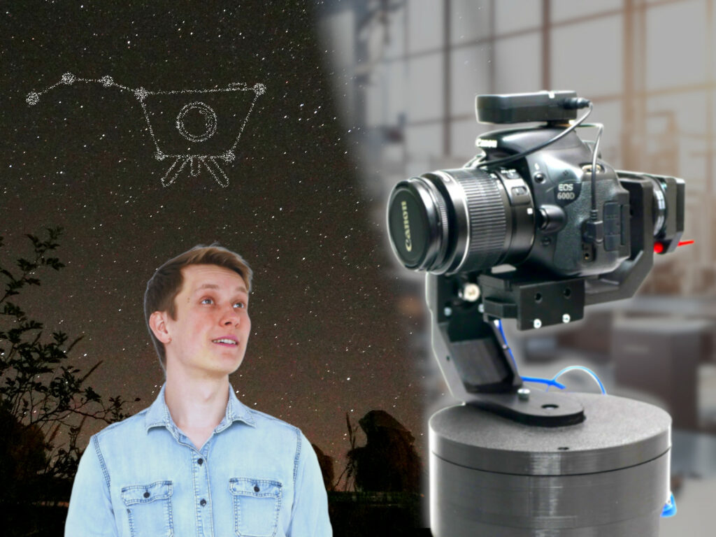
I have been always very fascinated with space. The easiest and 100% safe way to almost “touch” the space from the ground is astrophotography. Watching planets, comets, and other objects through a telescope is even better as you see it just through some lenses and mirrors with your eye without any electronics. But telescopes are expensive, very expensive. The one I got on my eighth birthday was more like a toy than a real telescope. I could still observe the moon up close but unfortunately nothing more, not even a single planet. But that wasn’t important back then, I had a telescope and I could stare at the night sky through it, that was enough. Over 15 years passed since then and my passion for space is still alive. In March 2023 I defended my bachelor thesis titled “StarTrckr – night sky tracking device” and got an engineering title in Control, Electronics, and Information Engineering. Here you can find more information about this open-source project.

IDEA

I am not 100% sure of when the idea for this kind of project was born. On any occasion throughout my life, I have been trying to get some nice pictures of the night sky with any kind of camera that was available. As I have been upgrading my gear and learning more about photography from time to time the images got better and better. You can see some of them below. While some of them are simply nice images I like the most the images that are definitely not that impressive. This one I simply took with my smartphone in the Belgian forest while lying on the ground with a group of friends from CubeSat Summer School organized by the European Space Agency (ESA). I also got some nice images of the Neowise Comet in 2020. But Starry Tree is my favorite so far.

But the more astrophotography images you take the more you realize that a simple camera and a tripod will only take you so far. Once your aspirations grow and you want to target deep sky objects (galaxies and nebulas) you will face a problem – Earth rotates. There are devices that can deal with that called star trackers. Most of them are either equatorial mounts – big 2-axis devices designed for telescopes. One of their axes must be aligned with Earth’s rotation axis in order to properly track the night sky. The other popular type is an alt-az mount. It also uses two axes but none of them is aligned with the celestial pole and because of that, they suffer from a problem called field rotation. You can track any object in the night sky but it will rotate on the sensor of your camera resulting in a blurry long exposure image. Initially, when thinking about this problem I wanted to design a small 3D-printed equatorial mount with just one motor rotating at exactly 15 degrees per hour (360 degrees/24h = 15 degrees/h – that’s how fast the Earth rotates!). But equatorial mounts are hard to set up properly, need a big tripod, and are usually too complex for a simple DSLR type of camera and lens I am using. Also building something that so many people built before wasn’t as exciting as creating something new. So I slowly started thinking about a different project, something new and completely different. That was long before my final semesters at the university.

At some point, I decided that alt-az mounts are minimalistic and simple and I like this kind of design. But the field rotation is a problem. A problem that can be solved. By simply adding another axis. Does it make sense to create a more complicated system? Yes, there are numerous advantages that I will mention later.


Check out my store and support my work!


DESIGN

The design started on a piece of paper. Even before that, I had been thinking about it a lot but my bachelor thesis pushed me to start working on it and this process started with some paper sketches.

These slowly turned into a proper CAD design. Sketching everything beforehand on a paper was a great way to think about the most important aspects of the project without being focused on dimensions and tools in Fusion360 – the program I used to design the whole project. Overall I designed 4 different versions. One was so bad that it is not even presented below. The first on the image from the left was blocking the movement on the axes (I thought it was not going to be a big problem but during testing, it was a serious imitation) so I designed the version in the middle with reinforced parts and motors flipped to the other side of the arms. The last version named v4 was not yet made. It features a bigger fork instead of one sided arm to increase the stiffness of the construction. All versions were designed to be printed on the most popular printers like ender3 or Prusa i3.

In the future, I am considering upgrading some parts (especially the arms) with laser-cut steel.

After printing and partial assembly that’s how the StarTrckr looks like. The base is composed of 3 parts that need to be stacked together.

After assembly and attaching the camera a complete system ready for testing looks like that.

ELECTRONICS

The design described above was only about the mechanical design and that is just a part of a project. Electronics is another essential part of getting it working properly. My PCB and schematic were designed in KiCad and later made by JLCPCB.

When I was working on the project there were big problems with the supply chain and a shortage of electronic components, especially microcontrollers. But there was one, always available, cheap, and programmable in Python. RP2040 from Raspberry Pi that was used in Pi Pico which I played with and liked a lot so I decided to design my PCB around this microcontroller fortunately the RP2040 documentation is really incredible and so detailed that designing your own custom PCB with this microcontroller is a great experience. The only problem is that an external memory chip is needed and it was quite expensive to buy. But I was able to just cheaply buy a module with this chip, desolder it, and solder to my PCB. I saved a lot of money on shipping and quite a lot of time that way.

Soldering went smoothly even though the RP2040 has very small pins. After checking everything under a microscope and with a multimeter it looked fine so I uploaded a simple test script and it worked on the first try! I was really happy to see the PCB working. I started the project so late that it just had to work, otherwise it would be hard to finish my thesis on time.

More information, a list of parts, and design files are available on GitHub.

PROGRAMMING

Thanks to the RP2040 microcontroller I was able to use MicroPython to program it. As a data science student, I love Python and I think it was a great choice as I was able to create the desktop software used to control the StarTrckr and the firmware for the control board in the same programming language. The code was divided into multiple files to make it easier to read. Probably the most interesting part is the 3D Bresenhams algorithm to move the tracker on all axes at once and the complicated algorithm running on the desktop computer with multiple vectors and a lot of calculations to easily rotate the tracker, calibrate it with Eart’s rotation axis and then track the sky. It might not be the most pretty piece of code but it works and I hope I will improve it in the future.

TESTING

As the deadline was approaching very fast I wanted to start testing the system but the weather was bad most of the time. It was December so that was to be expected. For that reason, the first “test” was performed indoors with Stellarium software on the computer. Of course, that is not a real simulation but I just thought that it might be a nice way to simply test if everything rotates properly. Of course, it wasn’t, it was rotating in the opposite direction so I just fixed that by adding a missed minus sign.

The first real outside test was performed in a village in Poland where light pollution is not as big as it is in the city where I used to live at the time. That was the setup, a simple table, StarTrckr with a DSLR, my computer, and a 3S Lipo battery to power the system.

And now we can look at the test images. To prove that the system works I took images with the very same settings and the camera was mounted on the tracker but for the first one, you will see the tracking was disabled and for the second one enabled. The ISO, exposure time, f-stop, and lens exactly the same, it was just the tracking that was on or off.

So here is the first one, as you can see the stars are blurred and we can see what is called star trails – the stars are not points but rather lines. In the corner you can see a piece of a building, it’s perfectly sharp because the camera was stationary.

In the second picture, the star trails are not that visible and stars are much closer to points. The building in the corner is blurred because the camera is rotating.

Why the stars are not perfect points? Because of no ideal alignment with the north star.

Test number two was performed in a bigger city where I lived at the time, light pollution is a serious problem there but I still wanted to try. This time I pushed the exposure time to 600 seconds so 10 minutes which was quite extreme but I really wanted to see what will be the difference in the images.

And here we can see perfect star trails when the tracking was off.

And here is the tracked image with the same settings.

Definitely not ideal points but much closer to that. And as I mentioned 10 minutes for this kind of setup with a basic camera and lens is quite extreme. It is much better to take more short exposures rather than a single long exposure as it is later easier to remove noise that way.

CONCLUSIONS

As mentioned at the beginning of this project was my bachelor thesis and thanks to finishing this project I obtained my bachelor’s title (in Poland we call that an engineering title). I was graded 5 for the project (the highest grade possible) and 5 for my whole course. It was the cherry on top of the 3.5 years I spent studying Control, Electronics, and Information Engineering. But that’s not the end! Right now I am almost finishing my master’s degree in data science and as my final project, I will continue developing my StarTrckr system.

I am really happy with the result of the project so far. The combination of so many different fields in one project was a great opportunity to learn and test different ideas. There is just one more thing to do. It has been my goal since I started working on this project – taking a nice image of the Andromeda galaxy. I hope it will happen soon and I will definitely share it with you.

And at the very end if you enjoy my projects and would like to support my work you can do it through my online store where I sell parts for my DIY CNC machine IndyMill and some parts for powder coating as well. You can support my work on Patreon or use YouTube super thanks. Simply subscribing to my channel and sharing the videos also helps a lot!

Happy making!

How to: DIY powder coating

This will be a brief introduction to DIY powder coating. I would like to present you all the tools you will need and a step-by-step process of how I do it.

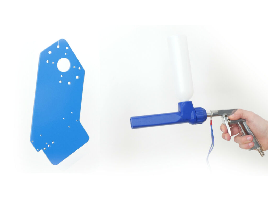
I got interested in powder coating and doing it on my own because most companies didn’t match my quality standards when it came to painting the steel plates for my CNC machine IndyMill. After a quick research, the idea of doing it on my own was born. I bought a cheap powder coating gun and used an old oven I used to have in my kitchen and achieved very decent results. Having full control over the painting process and handling the plates resulted in a higher quality of the painting job.

Why is powder coating better than conventional painting? It’s not as messy, toxic, or time-consuming and in the end results in a more robust surface finish. To powder coat you use a dry powder, it’s easy to clean, and even after applying it stays dry and doesn’t adhere to any surfaces (it needs to be heated to form a solid bond with the part). Because there are no solvents in the powder it’s way less toxic (but still safety is very important, wearing a proper mask, the powder is composed of super tiny particles that you really don’t want to breathe in, more about safety down below). Why is it quicker? Because you don’t need to wait for the paint to dry. 10-20 minutes in the oven and after cooling down the part is ready, no need to wait multiple hours until the paint is fully dry. Powder coating is usually more robust and harder than standard paints. As you can see it has many advantages but still is easy enough to do it in your own garage.

What you will need?

Powder coating may sound like you need a lot of expensive tools but don’t worry it’s not that bad. Here is a list of parts that are needed to start your powder coating journey:

  • Air compressor

The compressor I use is very old and still works fine. Perfectly you would use an oilless compressor for that but even with an oil one, it’s possible to powder coat with decent results. The bigger it is the better as it doesn’t need to turn on so often.

  • Oven

Do not use your oven at home! That is the most important part. You don’t want to cook food and powder coat paint in the same place. Buy an old oven or use the old one that is not in your kitchen anymore (that’s what I did). You can even buy something small like this one. And it will work fine for small parts.

  • Powder coating gun

There are plenty of expansive solutions for industry and just a few in the budget-friendly range. I found one that was very inexpensive and interestingly it is 3D printed. Because it has been working for me so well I ordered some more and now you can buy it in my store:

There are also additional empty containers available which are very useful if you want to paint multiple colors. I have been using the very same powder coating gun since I started to do it and it still works well, I have never faced a single problem, it’s easy to clean and also very durable. There are two different versions with US and EU plug. It’s a tribo-type powder coating gun so it needs to be grounded that’s why the plug has plastic pins.

  • Powder paint

It’s surprisingly inexpensive and there are all the possible colors from RAL available. Make sure that the powder paint works with the type of powder coating gun you have (tribo or corona). Usually, this paint works with any type of system but sometimes it is meant for only one of these. You can even find some powder paint on Amazon but I recommend finding something locally as it is way less expensive.

  • Hooks

I do recommend buying some solid steel hooks as it makes sit much easier to work with then DIY some hooks out of crappy materials on your own. These are so inexpensive and you can find many different versions that it’s just not worth it to make them on your own. For example, here you can find some.

  • Powder coating booth

While there are some options to buy a small booth for painting there is nothing cheap and small meant for powder coating. I built it on my own and it worked great. I am showing the build process in the video and below you can download the blueprints used for the build with all the dimensions for free to download.

Safety

Powder paint is composed of very tiny particles, particles that you definitely don’t want to inhale or get in your eyes this stuff is dangerous. When you powder coat even with really good filters, fans, and ventilation system there will always be a lot of particles flying around. That’s why you should always wear a proper respirator and eye protection. Also doing it without any fans and filters is not a good idea as these tiny particles if not filtered out of the air will fall and cover everything around your workshop. Having a separate room for that is a very good option. The respirator is something you should have in your workshop anyway, whenever you are cutting wood or steel it all results in tiny particles flying around you and getting into your lungs. If you are a maker and you like to make stuff take care of your health and safety so that you will be able to make more stuff in your life.

The mask I am using from 3M is very high quality and in my opinion, it’s a must-have in any workshop. Filters last 6 months, it’s very comfortable and will protect you not only while powder coating but also while cutting wood, etc. Considering the quality of it it’s surprisingly inexpensive.

Don’t be afraid and make it stop you from trying powder coating, it’s not as scary as it may sound. In fact, it is less toxic than normal spray painting. Just remember about a good mask and proper filtering.

DIY Powder coating booth

The booth was designed in Fusion360 and made mostly by hand out of MDF. I highly recommend building the booth out of plywood, MDF is really not the best choice.

There are three in my opinion super important parts of any powder coating booth.

  • Filtering system
  • Light
  • Rotating system

To build the filtering system I designed my own box fan that was 3d printed and used cheap BLDC motors. Unfortunately in Europe, box fans are not popular and in Poland, it’s impossible to buy a box fan. So making these on my own was the only choice for me. If you have access to box fans just buy something inexpensive.

You can use cheap LED strips to make very good light for your booth. I used the waterproof version of the LED strips but I don’t think it is necessary. With a simple plastic bracket bought in a hardware store, these were attached to the booth.

Rotating system was simply 3D printed. Additional big bearing and some wooden sticks resulted in a perfect little carousel for painting the parts and rotating them around. The bearing was used not only to rotate the part but also for grounding the part while painting.

Here you can download the blueprints for the booth:

You can see the full build process of the booth in the video linked at the beginning of this article.

At the end, I would to show you my old booth which was a 2-hour build out of pallet wood. It worked well for over a year! Warning, it’s ugly 🙂

Painting from start to finish

A step-by-step process of powder coating:

  1. Cleaning the parts

    I usually sand all the parts with a vibrating sander and then clean them with a paper towel. This works well for powder coating in my case. If you want, you can also use some chemicals to clean the parts and remove any oil or stuff on them. I mostly paint newly laser-cut steel or smooth aluminum parts, so I don’t have to do much. But if you’re painting old parts, you might need to spend more time cleaning and getting them ready for painting.
  2. Preheating (optional):
    It’s not a must, but sometimes I like to heat up my parts in the oven before painting. This makes the paint stick better, and I can finish painting faster. It’s a handy trick, especially if you have a bunch of parts to paint – saves a good amount of time. It could also be useful for tricky-to-paint parts. I haven’t tested it with nonconductive parts, but who knows, it might work for them too!
  3. Powder coating
    Set the air compressor pressure low, just a bit over 1 bar is good. Pour the powder paint into the container and begin gently applying a thin layer on the part. Aim for an even coat to get a smooth surface without any bumps or gaps. Make sure the entire part is covered in the color powder you’ve chosen; you shouldn’t see the part’s surface at the end. I usually start with the edges and holes, saving the larger areas for last.

    A great thing about powder coating (if you didn’t heat your part) is that if something goes wrong, you can blow off the powder with compressed air and start over.
  4. Oven
    Take a look at the instructions that come with your powder paint. Typically, you’ll need to set your oven to around 180°C (356 degrees Fahrenheit). The parts should stay inside for 10-20 minutes. Remember, this time is measured after the part reaches the mentioned temperature, so you might want to add a few extra minutes. If you take it out too soon, you might notice the coating is rough, not smooth. In my experience, even if you leave the parts in the oven for 30-40 minutes, nothing bad usually happens.
  5. Cooling down
    This step is pretty self-explanatory. You need to cool down the parts before using/packaging them or so on. It depends on the ambient temperature but usually after around 15-20 minutes, you should be safe to touch the parts. Check before grabbing the part and burning your hand!
  6. Ready
    Congratulations! Your parts are ready! You can be proud of yourself – from just an idea and some online research, you’ve reached the end with your first powder-coated part. I know the feeling, it’s exciting and empowering! But don’t stop there! Experiment and play with different techniques and materials to try and improve the process even more. How about mixing powder colors or coating different materials? Let me know how your experiments turn out!

And finally some examples of the parts I had powder coated:

DIY Mini Metal Brake

Simple metal bending tool that you can build with a drill and an angle grinder, no welding required!

Mini Metal Brake V1

When building my bachelor thesis project – the StarTrckr I noticed limitations of 3D printed parts. I couldn’t design my project how I wanted it to and still make it stiff to handle a DSLR camera. Plastic parts were completely ok for most of the project but 3D-printed arms (similar assemblies are used in camera gimbals) were flexing too much. So I decided that at some point I would upgrade parts for this project with metal parts, preferably laser-cut steel bent to 90 degrees. But the first step is always to make a prototype. I still haven’t tried machining steel with IndyMill so obviously, the prototype shall be made with aluminum, but how to bend it? I tried bending aluminum some time ago just with vice and I know how hard this process is and the results are not satisfactory for me. For that reason, I knew that to create nice prototype parts I need a metal brake (metal bender, bending machine). Tool like this seems easy to build so that’s when I decided to design it, buy the parts and just try to make it as good as I can keeping the budget low and minimal tools required.

Parts

One of the challenges was not to use welding in this project and the second one was to use only the parts available at the popular local hardware store in Poland. If you are not familiar with polish hardware stores let me tell you there is not a lot that you can buy there. For that reason project is built with few basic and hopefully easy-to-buy worldwide steel elements. Of course, this instruction is only an example of how I built it and I advise you to use it only as a reference and adjust the project to your needs. If there are other similar components you already have or can buy cheaper, feel free to do that!

NameAmount
L-shaped steel profile 35x35mm 300mm long2
L-shaped steel profile 25x25mm 200mm long1
Steel profile 20x20mm 250mm long2
hinge 40x40mm2
M8x30 screw2
M8 washer2
M5x25 screw4
M5 nut4
M4x6 screw12
M4 nut (optional)12

All elements and the dimensions I have chosen are based on my needs, I know that I am not going to bend some long materials so I preferred to keep the dimensions compact. Here are drawings of the profiles with all the dimensions just to clarify everything:

The M4 nuts mentioned in the table are optional because I tapped the threads in the holes for M4 screws and that way the nuts are not required. Keep in mind that the material that we are using is rather thin (the profiles I have used are just 2mm thick) so the threads are not super strong but so far work great and if there are any problems I can always add nuts later.

It might be hard for you to buy the same hinges that I used in this project so the holes pattern might differ. Make sure to constantly check if everything fits together as you build it and drill the holes for the hinges after checking if they fit. Also, label the holes based on hinges placement and holes pattern. If you use different components do not follow the drawings below very strictly.

NameLink
Drillhttps://amzn.to/42WeWnA
Drill press (optional)https://amzn.to/3zpx5wp
Angle grinderhttps://amzn.to/3zr6mj8
Metric tap sethttps://amzn.to/40RhbH0

The tools mentioned above are required for the project, except the drill press it’s very helpful to drill some holes but you can also easily drill them with a cordless drill. As you will see later you can even drill the holes with an old grandpas hand powered drill 🙂

Cut & drill

The drawings presented below should clarify all the holes placement and lengths of the profiles. If the images are too small you can drag and drop them to a new tab and zoom in.

We will need M4 and M8 taps to tap the holes as presented in the diagram below. The rest of the holes are simply drilled.

3 holes on each end of the profile labeled M4 shall be tapped with an M4 tap, that’s where the hinges will attach.
This is the 25x25mm L profile, holes need to be drilled at the corner of the profile. That’s where two M8 screws will be attached to clamp down the material.
5mm holes were drilled in the handles to attach them to the profile.

Unlike most designs of metal brakes, my brake attaches to the vice as it is easier and quicker to set up. For that reason, one of the 35×35 profiles (the one with holes for the handles) needs a cutout. I am using 150mm vice so that’s why my cutout is slightly bigger. Adjust this dimension to your own vice.

Additionally having the brake attached to a vice solves one additional problem and that is all the screws that stick out from the bottom of the other profile that make it impossible to attach to a flat surface. This problem can be solved by adding a piece of wood to the bottom but I am not a fan of this option.

Vice cutout.

After cutting & drilling you might want to check if everything fits together nicely. Before final assembly it’s a good idea to paint your project to give it a professional look 🙂

Painting – powder coating

I like adding a professional touch to my projects and making them as cool as I can. Also, additional protection from corrosion is helpful so that it lasts longer. For that reason, after a test fit I disassembled the whole project including the hinges and powder-coated everything blue and black.

But how did I do that? I have my own cheap and simple powder coating setup. But wait, there is more! You can buy the same powder coating gun that I am using from my store:

This is a very simple-to-use gun perfect for a small project like this one or even small-scale manufacturing because I am also using it to paint parts that I sell for my IndyMill CNC machine. All you need in addition to the powder coating gun is an air compressor and an oven, that’s it. Powder coating is not only simple but also efficient, inexpensive and fast as you don’t have to wait for the paint to dry, it just has to cool down.

That’s me powder coating the parts, the booth is something I have to work on and improve as well as creating a better filtration system.

Your safety is very important when powder coating so you need a filtration system (don’t look at mine, it’s not good enough), a very good mask (I am using a 3M mask and it’s perfect), goggles, and gloves.
Parts drying after powder coating. The whole process takes about 30 minutes. 5 minutes painting, 15 minutes in the oven, and 10 minutes cooling down.
Parts after homemade powder coating.

There is one thing I should mention, tapping the holes and then painting is not the best idea because the paint will get inside the threads and you will need to retap them, otherwise driving screws will be hard. I tapped the holes before painting for a reason – I wanted to assemble everything before painting to test if it works ok or still require some refinement.

Assembly

Once the MiniMetalBrake was painted to your favorite colors it’s time to assemble it according to the drawings presented below. Those are pretty self-explanatory so I will only point out the most important steps there.

When joining together two L profiles make sure that the top surfaces are perfectly parallel and flat. It’s a good idea to clamp them in a vice together and then join with hinges (actually I used the same technique when drilling holes for the hinges).

Two 35x35mm L profiles.
Hinges attached to the profiles with M4 nuts.

The following step is optional. I tapped the holes with M4 tap and it works ok so I didn’t use nuts but I added it there just to show you that it’s a possibility.

Optional M4 nuts.

Here I want to mention one possible improvement that is super easy to implement. Springs. Adding springs on the screws is a great improvement in user experience as the profile that clamps down the material will rise on its own. I had no such springs around so that’s something I will add in the future.

M8x30 screws are attached with washers through a 25x25mm profile that clamps down the material.
Handles are attached with M5 screws and nuts.
Wireframe view of the completed MiniMetalBrake.
Render view of the MiniMetalBrake.

What can you bend?

There was one goal as I mentioned in the beginning and that was to create metal arms for the star tracker so the first thing I made was exactly that. I designed an arm with sheet metal tools in Fusion360, machined the aluminum piece with IndyMill, and bent it with a MiniMetalBrake. Later the piece was powder-coated black to make it look professional and match with other parts in the StarTrckr.

Unfortunately, I had to cheat a bit when bending this piece and add additional support. The steel profile was bending a lot when I tried to bend this 3mm thick aluminum. So one future upgrade would be to add some flat pieces of steel attached to the handles to support the part more and reduce the flexing in the steel profile.

3mm thick aluminum machine on IndyMill, bent with MiniMetalBrake and powder-coated black. Amazing result and improved stiffness. There are 2 more arms to be replaced in the StarTrckr.

And then I wanted to try something more complicated so I designed a one pice phone holder. It is also made out of aluminum with IndyMill, and the material thickness is 1.5mm.
This time machining was hard, I have no idea what kind of aluminum was that but milling it was almost impossible. At the end after a lof of sanding, I got it to look somehow decent and after powder coating, most imperfections are not visible anymore.

Simple one-piece phone holder.

The small size makes it easy to store for example on your tool wall. Attaches quickly to the vice and hopefully will be often used in future projects. Machining aluminum with DIY CNC is cool but combined with a metal brake it literally adds another dimension to your parts.

MiniMetalBrake is easy to store, for example on your tool wall.

Thanks for reading through the whole project! I hope you liked it and that maybe one-day MiniMetalBrake will show up in your workshop too! I am thinking about redesigning the machine to laser cut the parts out of thicker steel and improve some of its weak points and offer a kit for it in my store. Are you interested? Send me an email: nikodem@indystry.cc

3D Printed duct fan

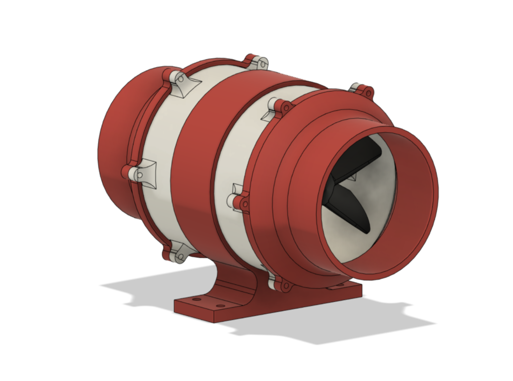
This is a 3D printed duct fan that can be used with a 775 motor or a popular BLDC (for example 2212). It can obviously also be adapted to any other motor. It’s an open-source project so below you can find STL files and .F3D files of a project so that you can easily modify and adapt it to your needs.

Consider supporting my work:

Become a Patron!

Files

Below you can download ZIP with all the STL and F3D files of the duct fan, fans, and air filter attachments that I designed. You can also find here the PDF with all of my measurements and plots. Feel free to print, modify and share with others.

Tests and measurments

In the beginning, there was just an idea for a simple duct fan but later I thought that I can optimize it and design a better fan. In order to do that I experimented a lot and measure the performance of each fan while noting everything in a spreadsheet. Later I made a lot of plots to show how each fun perform and you can see all of that here:

https://docs.google.com/spreadsheets/d/1bWz74lslCTUJS_hIYJnpoS_NEaYTMo8m/edit?usp=sharing&ouid=113317919185968062988&rtpof=true&sd=true

You can also find a PDF version of that in the ZIP above.

Here you have 6 most interesting plots where you can observe the difference between performance of each fan and how the measuring method influences the end result.

How to build a robot?

Robots are cool, I think we all agree on that. Right here I would like to give you a short introduction to all the topics that you will most likely face while building your first robot. In the beginning, I just wanted to say no worries, building simple robots is not hard at all, most of it doesn’t even require any soldering (sometimes you may need to solder cables to motors, but for simple robots that’s the only soldering required).

I also wanted to point out the difference between a robot and not a robot. Some tutorials refer to an RC car as a robot but in reality robot is a device that can work on it’s own. At the same time it’s not about fancy futuristic artificial intelligence or humanoid robots, it’s about simple tasks that are solved by the robot completely without human interaction. So a line follower or an obstacle avoiding robot are great examples of ROBOTS while a “robot” and a human with a remote next to it is not a robot.

Keep in mind that this is not a complete tutorial with code, schematic and DIY instruction. It’s meant as introduction to all the topics you should know about in order to even start and understand some of the robotics tutorials so that instead of mindlessly following those you understand what’s going on.

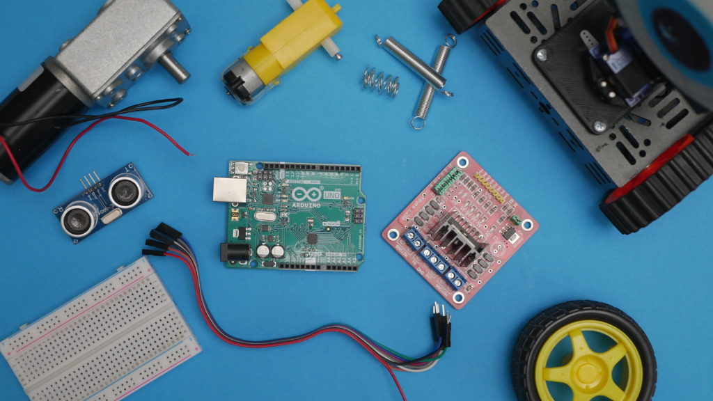
If you want to start easily with a kit, you can check out something like this with all the parts, chassis, motors, sensors, and Arduino. If you prefer to buy components individually check out the list below.

Here you can see a short one minute introduction video, and to learn more about all the topics continue reading:

Microcontroller

Microcontroller is a brain of the robot, all the logic, conditions and calculations are performed in here. To simplify it we can say that microcontroller is just a very very simplified computer, the internal structure is more or less similar. There is no screen or keyboard, just a chip with pins. By writing the program you can read pin states set conditions (if statements for example) do some math and set output pins conditions or communicate with other modules, sensors etc.

There are a lot of different types of microcontrollers but if you are just starting you should take a look at Arduino UNO (which is actually more than just a microcontroller, it uses Atmega328 as a microcontroller but Arduino is rather an ecosystem and collection of development boards). Any Arduino board is very easy to start with and Arduino UNO is additionally quite affordable (Original boards start at 23 USD or you can buy a Chinese Arduino clone for 5 USD). With UNO you can build blinking LEDs, learn electronics and programming, simple robots, home automation, measuring devices and even CNC machines! If you need more pins (trust me if you are just starting you don’t need more pins) you can buy Arduino Mega.

NameStore 1Store 2
Original Arduino UNOhttps://bit.ly/2MuCKMwhttps://bit.ly/3ormF7N
Clone Arduino UNOhttps://bit.ly/3t5gk59https://bit.ly/3osuWIi
Original Arduino Megahttps://bit.ly/2YnfYsQhttps://bit.ly/3pt5vro
Clone Arduino Megahttps://bit.ly/3aqqXHBhttps://bit.ly/2M3BsZf

Of course Arduino is not the only way to go. You can read about programming STM microcontrollers, AVR, or lately released Raspberry Pi Pico (programmed with C++ or Python). There are some more advanced boards like Maix Sipeed with an integrated screen and camera programmed with Python. You can also take a look at single-board computers like Raspberry Pi 4B or BeagleBone Black. But all of those examples are probably not the best for beginners.

Sensors

In order to build a robot (not an RC car) we need sensors. Sensors are devices that measure physical things and transform those readings into electrical signals so that we can read those with microcontroller. For example, to build object avoiding robot we need an ultrasonic sensor that will measure the distance between a robot and an obstacle. This distance or actually two-way time of travel of sound that is processed into the distance can further be processed to decide if the obstacle is close enough to stop the robot or turn. With 2 conditional statements (if(…){}) you can write a simple program for such a robot.

Another popular sensor for simple robots is a line sensor that can be used to build a line follower, that is a robot that follows the black line. By using three of those sensors at the front of the robot you can write a simple program that will drive forward when the line is detected by the sensor in the middle, if the line is detected by the right sensor it should turn right, and if the left sensor detects line you need to turn left. This is a simple example of a not really efficient program for a line follower but it works really well 🙂

There are other types of sensors, there is a sensor to measure everything you can think of air quality, pressure, soil pH sensor, LIDARs, movements sensors etc. Once you get more familiar with basic sensors you can start playing with those a bit more advanced. Ultrasonic sensor and line sensor are probably the easiest to start with and pretty straight forward to use.

NameStore 1Store 2
Line Sensorhttps://bit.ly/39q4qLxhttps://bit.ly/2MxQTbW
Ultrasonic Sensorhttps://bit.ly/3t1Quz7https://bit.ly/2YjCqTD
Sensor Kithttps://bit.ly/3aqzXfRhttps://bit.ly/39rnmJT

Motors

There is many options when it comes to motors for robotics but because this is an introduction I will focus only on simple and cheap motors. You should pay attention to the rated voltage and current of the motors. Usually, you should look for motors with voltage of about 5 to 12V. There should be a way to mount wheels or you will have to look for a DIY solution. In order to increase the torque and lower the RPM motor should have a built-in gearbox. To start I recommend those plastic yellow motors, those are not great and you wouldn’t build the most amazing robot ever with those but to start those are great!

NameStore 1Store 2
Yellow Motorshttps://bit.ly/3orwWknhttps://bit.ly/3pseObk
Small Motorshttps://bit.ly/3oqqgTmhttps://bit.ly/3adWmMX
Bigger Motorshttps://bit.ly/3qZZVxbhttps://bit.ly/3pthhSC

Motor driver (H Bridge)

There is no way to drive a motor directly with an Arduino, don’t even try because you will break it. In order to control the motors we need a motor driver also called H bridge. Again there is a lot of options and most of them are very similar. Main differences are max voltage and current that can be handled by a driver or some additional features. Some simple and popular drivers are listed below.

NameStore 1Store 2
L298https://bit.ly/36h9IH5https://bit.ly/3cgeLvq
L9110Shttps://bit.ly/3acjcVlhttps://bit.ly/3qYZyTI

Cables, Breadboards

Obviously, you will need some cables and a breadboard to connect everything together. They’re nothing complicated, buy some female-female, female-male, male-male cables. When it comes to breadboard use a bigger one for bigger projects and a smaller one for smaller projects, usually power rails on the sides are very useful.

NameStore 1Store 2
Cableshttps://bit.ly/2L20vLGhttps://bit.ly/2M2yGDx
Breadboardhttps://bit.ly/3cj6t67https://bit.ly/3t3MGgP

Chassis

In order to attach everything together, you will need a chassis. You can buy a set with chassis, motors and wheels or you can try to find your own DIY solution and make a chassis out of plastic or even cardboard (that’s how I built my first robot).

NameStore 1Store 2
Chassis 1https://bit.ly/3t3LJF7https://bit.ly/3cfuaw1
Chassis 2https://bit.ly/3a9Ebbmhttps://bit.ly/3cnsX5N

Batteries

The battery is always a really problematic part of building robots. The most common choice is a LiPo battery but it’s a little bit dangerous, you have to take care of it and be careful because discharging the cells under 3.2V may damage the battery. Those batteries are sold as 1S, 2S, 3S and so on which means one, two or three cells because each cell has a nominal voltage of 3.7V a two-cell battery has a nominal voltage of 7.4V (and a max voltage of 8.4V). Batteries vary with capacity, the bigger the capacity the longer you can power the robot. There is also max current that can be drawn from a battery this is labeled as for example 10C and it means that capacity multiplied by 10 will give the max amperage that you can draw from a battery.

Another (probably safer) way to go is to use protected 18650 batteries. It’s also more complicated because you need to create a battery pack on your own and combine a few of those batteries in parallel or in series. Professionally those batteries are spot welded together but you can just easily use a battery box to keep them together.

I don’t recommend going with AA or AAA batteries as you will need to recharge or replace those very often (it’s not good for the climate and your wallet) and the max current of those isn’t enough for some motors.

NameStore 1Store 2
2S LiPohttps://bit.ly/3iUpE7qhttps://bit.ly/2M2ILAn
3S LiPohttps://bit.ly/3qX8sRwhttps://bit.ly/2M2ILAn
4S LiPohttps://bit.ly/3iWMQSkhttps://bit.ly/2M2ILAn
18650 Batteryhttps://bit.ly/3a4ys6whttps://bit.ly/3orRskO
18650 Boxhttps://bit.ly/3a9hIv7https://bit.ly/36jr8Dh

Programming

A lot of people are scarred by programming, I am not really sure why. Programming is easy, you don’t need math to create simple robots! If you have any experience with C++ or similar programming languages you can start programming Arduino right now. If you don’t no worries, there is a lot of great tutorials and examples online. Once you start and try to write your own programs you will realize that it’s not that hard.

You can find some cool tutorials on official arduino website:

https://www.arduino.cc/en/Tutorial/HomePage

Or just type “Arduino tutorial” into YouTube and you will find thousands if videos on this topic!

I hope this article helped you a bit with your robotics journey! If so don’t forget to share with friends and share you progress on Instagram by tagging me: @nikodembartnik and @indystry

Have a nice day!

How to build 3D printed Dremel CNC?

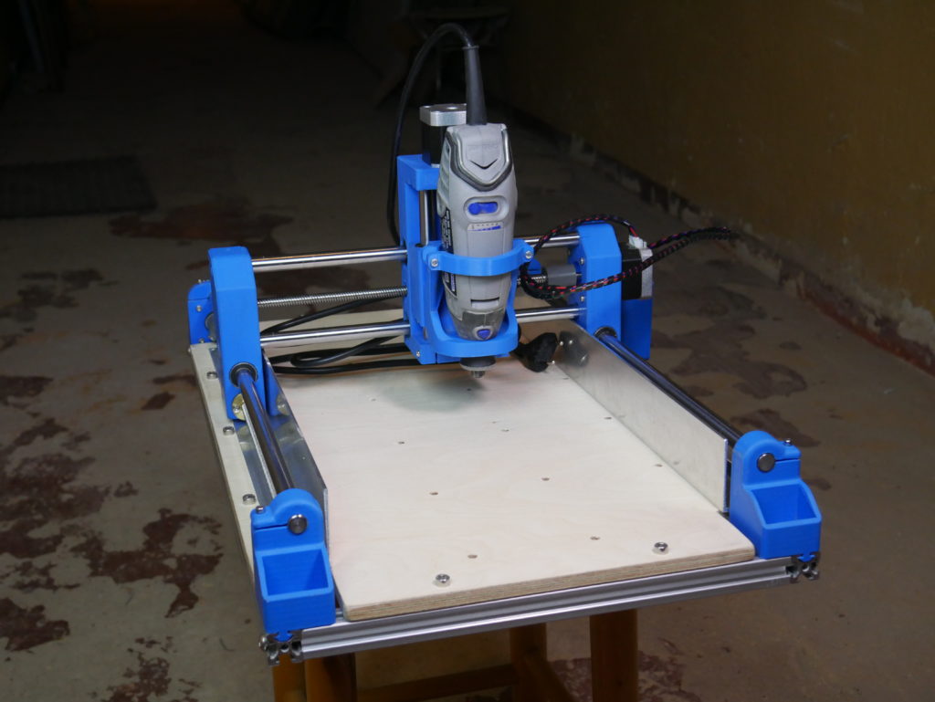
Try typing Dremel CNC to Google or Youtube, the internet is filled with my videos and tutorials about building 3D printed Dremel CNC. I kind of feel just like repeating over and over the same content and that is creatively hard for me because I like creating new stuff the most and not focusing on past projects.

At the same time, I understand that a lot of people want to build DIY Dremel CNC because it’s simple, cheap, and inexpensive, totally understandable! A CNC machine that can be easily 3D printed and assembled with easy to buy components, that was the goal of this project, and looking at reviews of hundreds of makers all around the world I think the project turned out perfectly! I am more than happy that such a simple idea of mine can help so many makers, businesses and people. As you may know, I am working on a new bigger CNC machine called IndyMill, that’s why I created this website to share all the info about this machine, release files, and maybe even create a small business out of that! But I don’t want to forget about Dremel CNC and I know there is still a lot of people that want to build it but don’t know where to start. That’s why I made this post, actually, the first one on indystry.cc, I hope to make some more in the near future 🙂 Let’s start!

Continue reading “How to build 3D printed Dremel CNC?”