Simple metal bending tool that you can build with a drill and an angle grinder, no welding required!
When building my bachelor thesis project – the StarTrckr I noticed limitations of 3D printed parts. I couldn’t design my project how I wanted it to and still make it stiff to handle a DSLR camera. Plastic parts were completely ok for most of the project but 3D-printed arms (similar assemblies are used in camera gimbals) were flexing too much. So I decided that at some point I would upgrade parts for this project with metal parts, preferably laser-cut steel bent to 90 degrees. But the first step is always to make a prototype. I still haven’t tried machining steel with IndyMill so obviously, the prototype shall be made with aluminum, but how to bend it? I tried bending aluminum some time ago just with vice and I know how hard this process is and the results are not satisfactory for me. For that reason, I knew that to create nice prototype parts I need a metal brake (metal bender, bending machine). Tool like this seems easy to build so that’s when I decided to design it, buy the parts and just try to make it as good as I can keeping the budget low and minimal tools required.
Parts
One of the challenges was not to use welding in this project and the second one was to use only the parts available at the popular local hardware store in Poland. If you are not familiar with polish hardware stores let me tell you there is not a lot that you can buy there. For that reason project is built with few basic and hopefully easy-to-buy worldwide steel elements. Of course, this instruction is only an example of how I built it and I advise you to use it only as a reference and adjust the project to your needs. If there are other similar components you already have or can buy cheaper, feel free to do that!
| Name | Amount |
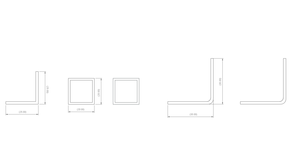
| L-shaped steel profile 35x35mm 300mm long | 2 |
| L-shaped steel profile 25x25mm 200mm long | 1 |
| Steel profile 20x20mm 250mm long | 2 |
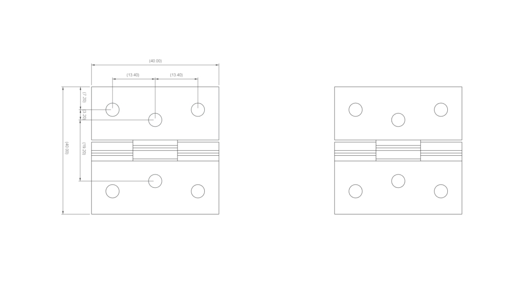
| hinge 40x40mm | 2 |
| M8x30 screw | 2 |
| M8 washer | 2 |
| M5x25 screw | 4 |
| M5 nut | 4 |
| M4x6 screw | 12 |
| M4 nut (optional) | 12 |
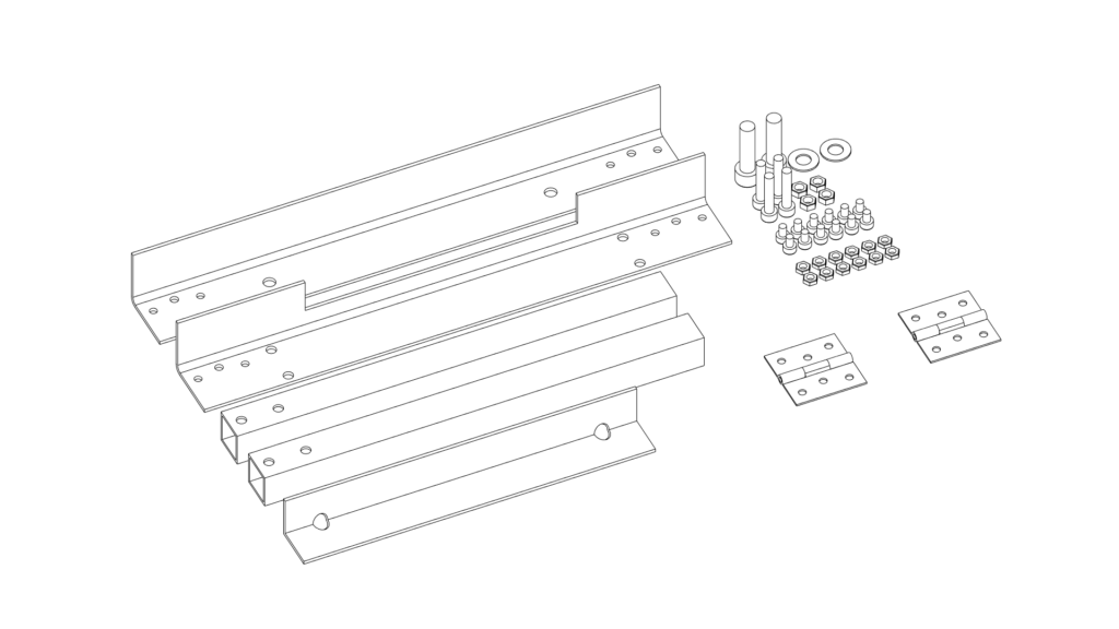
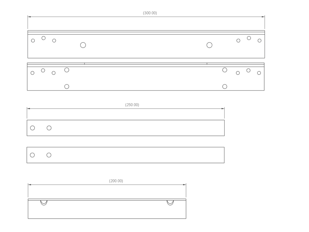
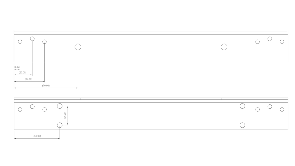
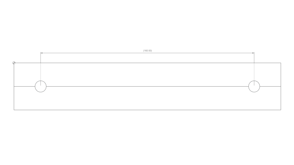
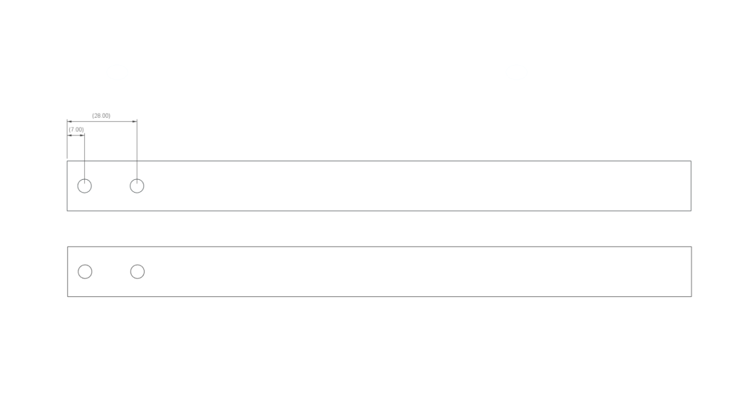
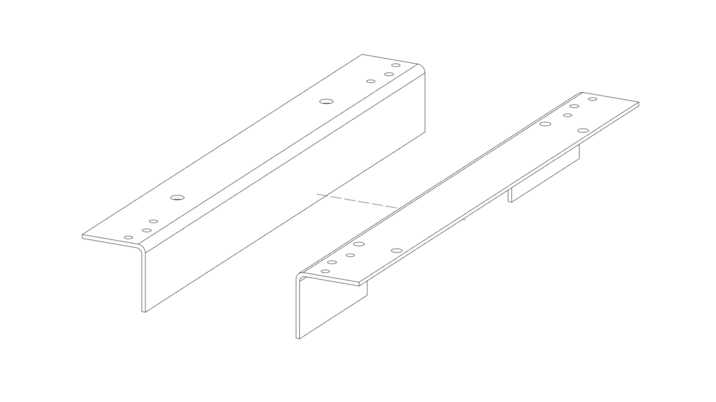
All elements and the dimensions I have chosen are based on my needs, I know that I am not going to bend some long materials so I preferred to keep the dimensions compact. Here are drawings of the profiles with all the dimensions just to clarify everything:
The M4 nuts mentioned in the table are optional because I tapped the threads in the holes for M4 screws and that way the nuts are not required. Keep in mind that the material that we are using is rather thin (the profiles I have used are just 2mm thick) so the threads are not super strong but so far work great and if there are any problems I can always add nuts later.
It might be hard for you to buy the same hinges that I used in this project so the holes pattern might differ. Make sure to constantly check if everything fits together as you build it and drill the holes for the hinges after checking if they fit. Also, label the holes based on hinges placement and holes pattern. If you use different components do not follow the drawings below very strictly.
| Name | Link |
| Drill | https://amzn.to/42WeWnA |
| Drill press (optional) | https://amzn.to/3zpx5wp |
| Angle grinder | https://amzn.to/3zr6mj8 |
| Metric tap set | https://amzn.to/40RhbH0 |
The tools mentioned above are required for the project, except the drill press it’s very helpful to drill some holes but you can also easily drill them with a cordless drill. As you will see later you can even drill the holes with an old grandpas hand powered drill 🙂
Cut & drill
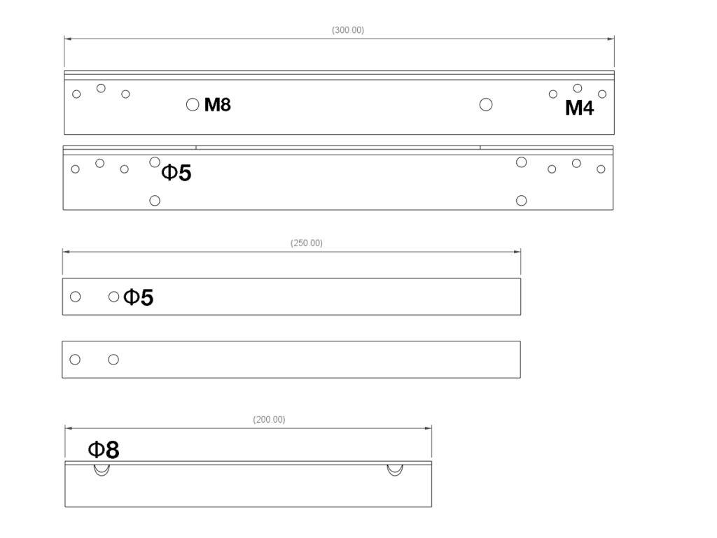
The drawings presented below should clarify all the holes placement and lengths of the profiles. If the images are too small you can drag and drop them to a new tab and zoom in.
We will need M4 and M8 taps to tap the holes as presented in the diagram below. The rest of the holes are simply drilled.
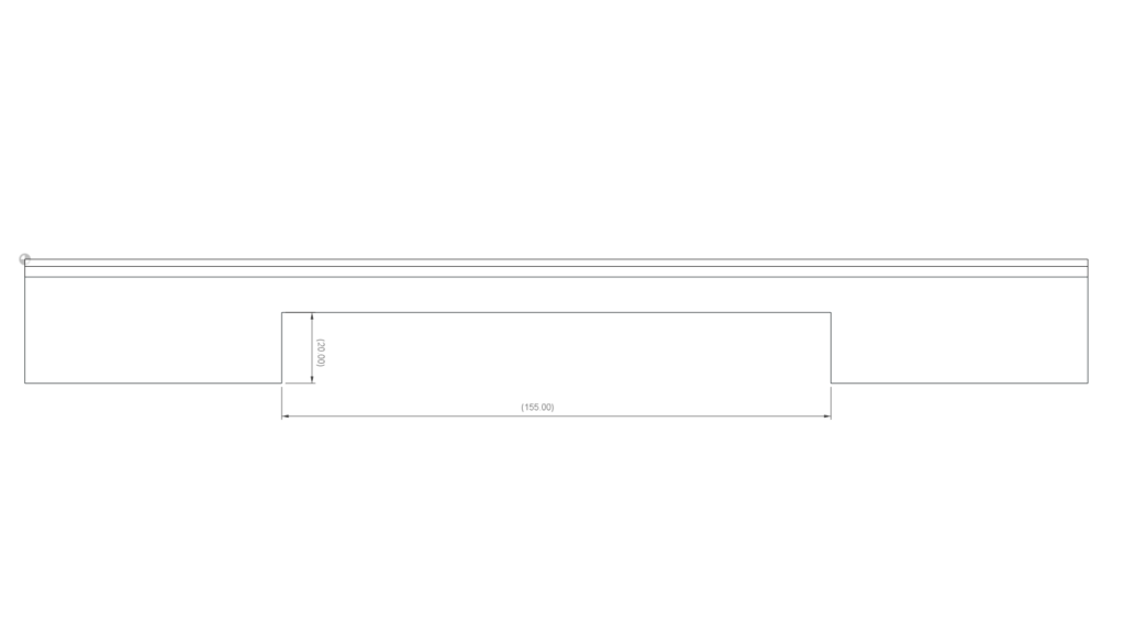
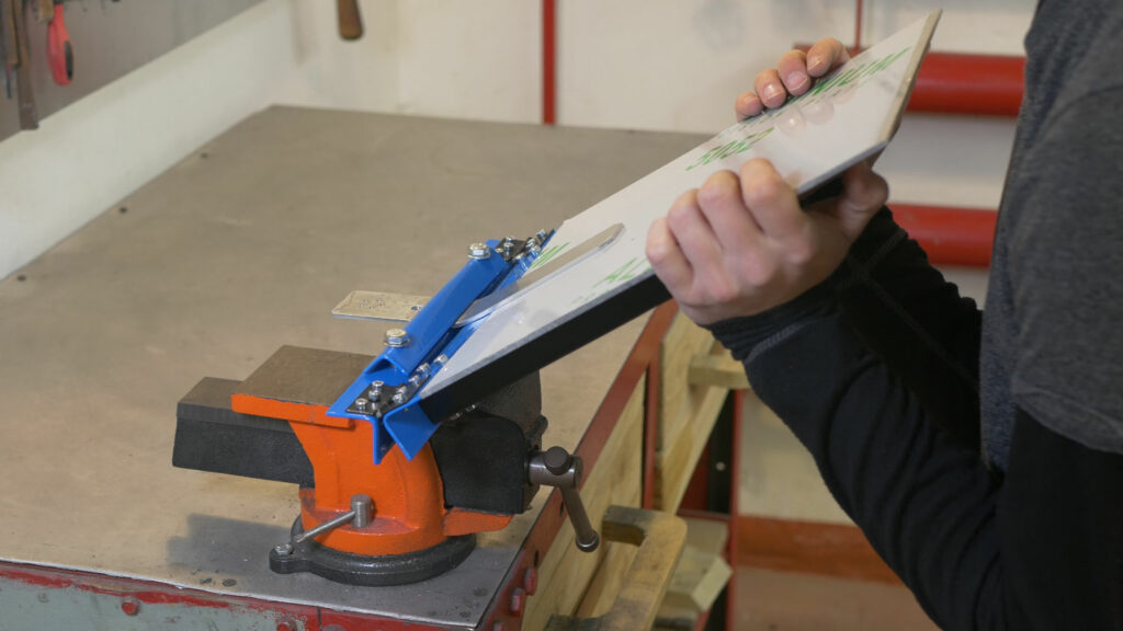
Unlike most designs of metal brakes, my brake attaches to the vice as it is easier and quicker to set up. For that reason, one of the 35×35 profiles (the one with holes for the handles) needs a cutout. I am using 150mm vice so that’s why my cutout is slightly bigger. Adjust this dimension to your own vice.
Additionally having the brake attached to a vice solves one additional problem and that is all the screws that stick out from the bottom of the other profile that make it impossible to attach to a flat surface. This problem can be solved by adding a piece of wood to the bottom but I am not a fan of this option.
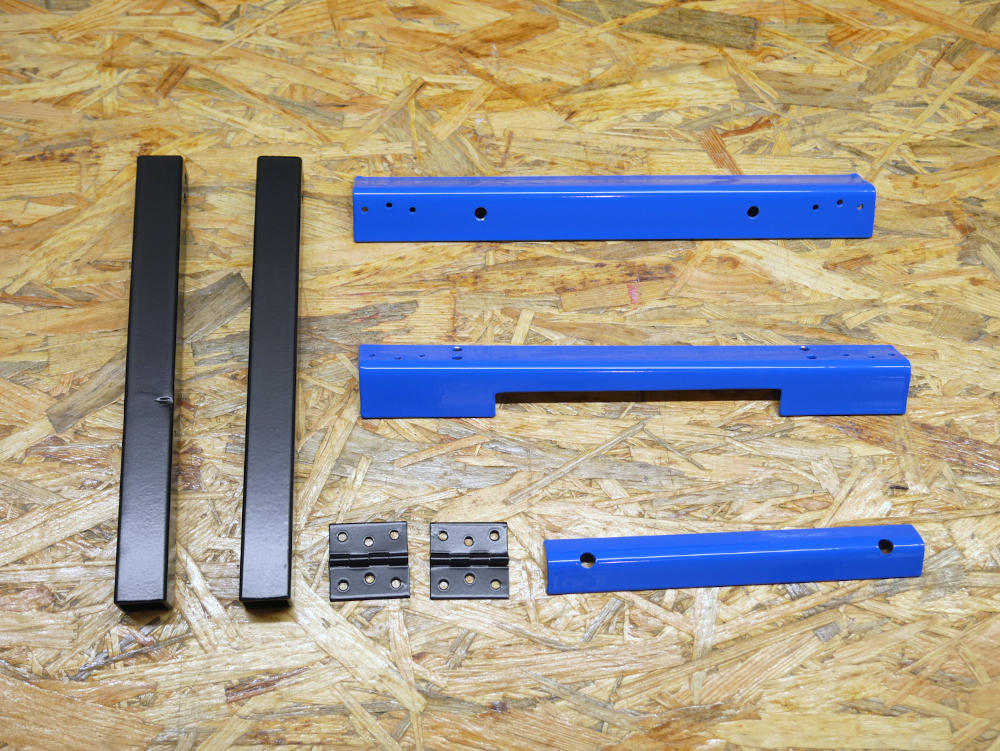
After cutting & drilling you might want to check if everything fits together nicely. Before final assembly it’s a good idea to paint your project to give it a professional look 🙂
Painting – powder coating
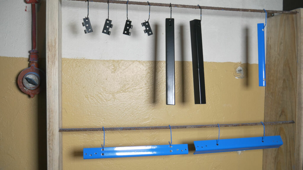
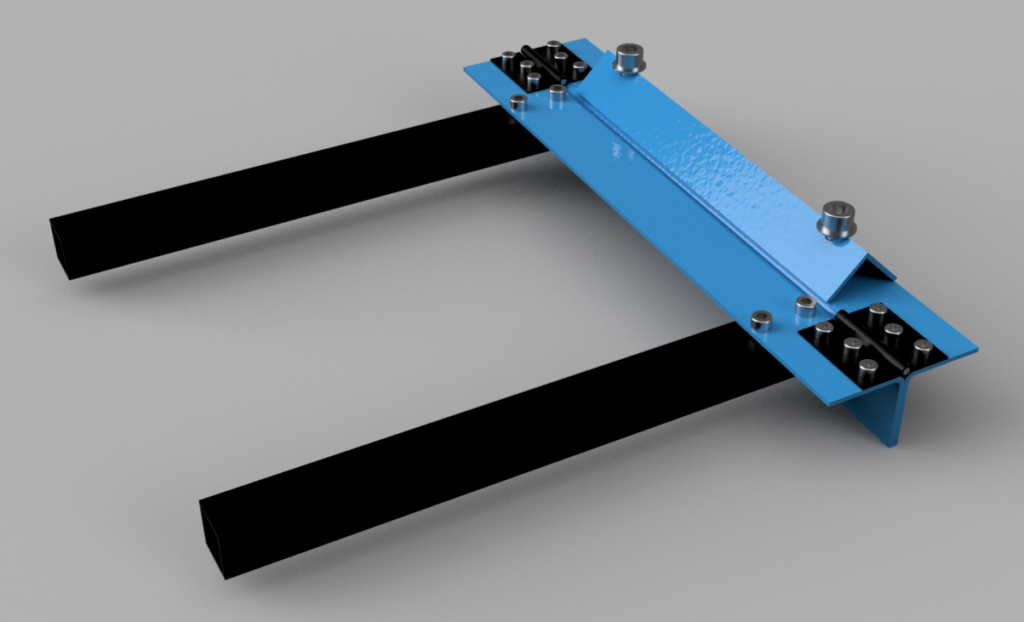
I like adding a professional touch to my projects and making them as cool as I can. Also, additional protection from corrosion is helpful so that it lasts longer. For that reason, after a test fit I disassembled the whole project including the hinges and powder-coated everything blue and black.
But how did I do that? I have my own cheap and simple powder coating setup. But wait, there is more! You can buy the same powder coating gun that I am using from my store:
-
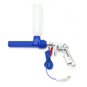 Powder Coating Gun$109,00
This is a very simple-to-use gun perfect for a small project like this one or even small-scale manufacturing because I am also using it to paint parts that I sell for my IndyMill CNC machine. All you need in addition to the powder coating gun is an air compressor and an oven, that’s it. Powder coating is not only simple but also efficient, inexpensive and fast as you don’t have to wait for the paint to dry, it just has to cool down.
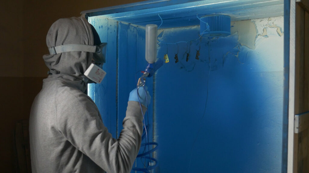
That’s me powder coating the parts, the booth is something I have to work on and improve as well as creating a better filtration system.
There is one thing I should mention, tapping the holes and then painting is not the best idea because the paint will get inside the threads and you will need to retap them, otherwise driving screws will be hard. I tapped the holes before painting for a reason – I wanted to assemble everything before painting to test if it works ok or still require some refinement.
Assembly
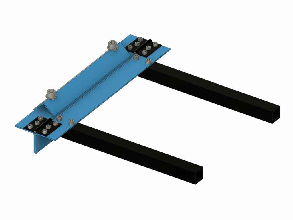
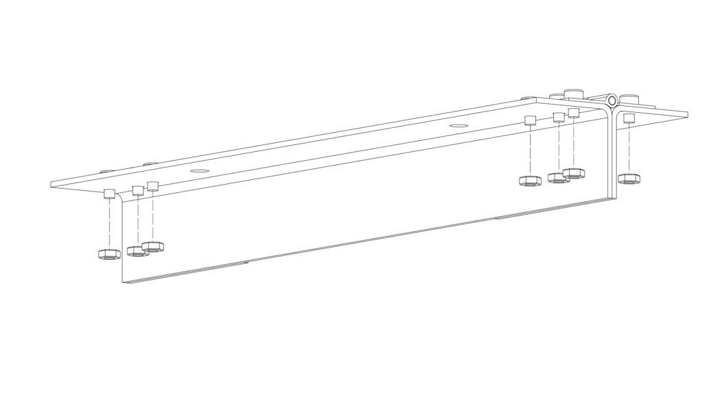
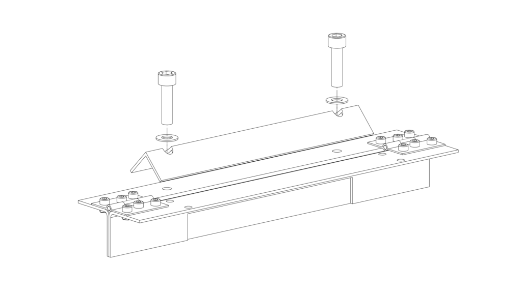
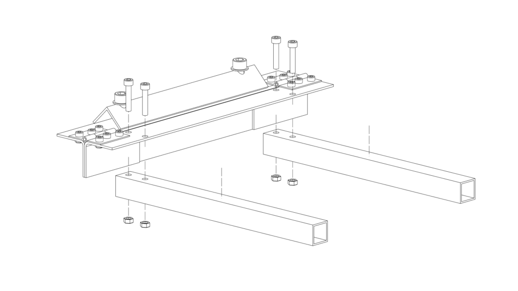
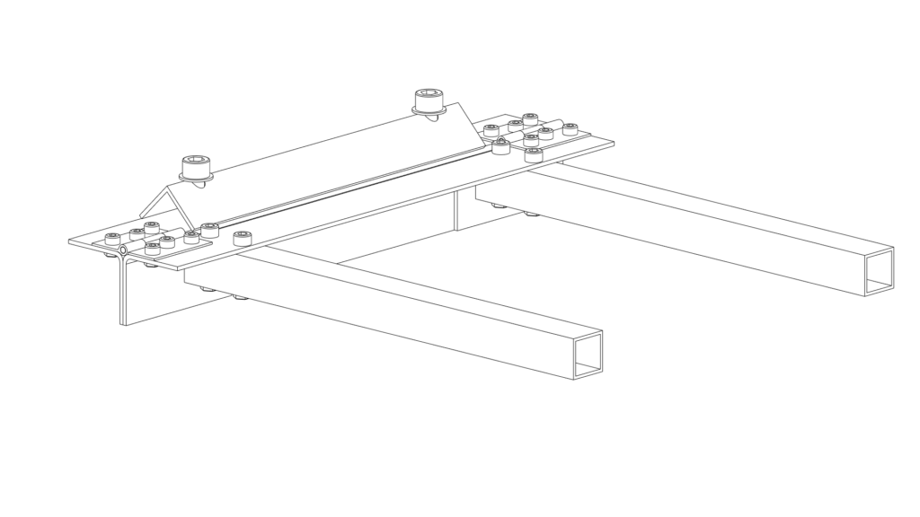
Once the MiniMetalBrake was painted to your favorite colors it’s time to assemble it according to the drawings presented below. Those are pretty self-explanatory so I will only point out the most important steps there.
When joining together two L profiles make sure that the top surfaces are perfectly parallel and flat. It’s a good idea to clamp them in a vice together and then join with hinges (actually I used the same technique when drilling holes for the hinges).
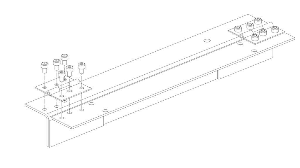
The following step is optional. I tapped the holes with M4 tap and it works ok so I didn’t use nuts but I added it there just to show you that it’s a possibility.
Here I want to mention one possible improvement that is super easy to implement. Springs. Adding springs on the screws is a great improvement in user experience as the profile that clamps down the material will rise on its own. I had no such springs around so that’s something I will add in the future.
What can you bend?
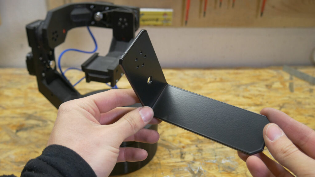
There was one goal as I mentioned in the beginning and that was to create metal arms for the star tracker so the first thing I made was exactly that. I designed an arm with sheet metal tools in Fusion360, machined the aluminum piece with IndyMill, and bent it with a MiniMetalBrake. Later the piece was powder-coated black to make it look professional and match with other parts in the StarTrckr.
Unfortunately, I had to cheat a bit when bending this piece and add additional support. The steel profile was bending a lot when I tried to bend this 3mm thick aluminum. So one future upgrade would be to add some flat pieces of steel attached to the handles to support the part more and reduce the flexing in the steel profile.
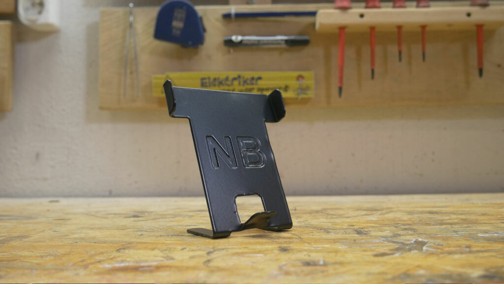
And then I wanted to try something more complicated so I designed a one pice phone holder. It is also made out of aluminum with IndyMill, and the material thickness is 1.5mm.
This time machining was hard, I have no idea what kind of aluminum was that but milling it was almost impossible. At the end after a lof of sanding, I got it to look somehow decent and after powder coating, most imperfections are not visible anymore.
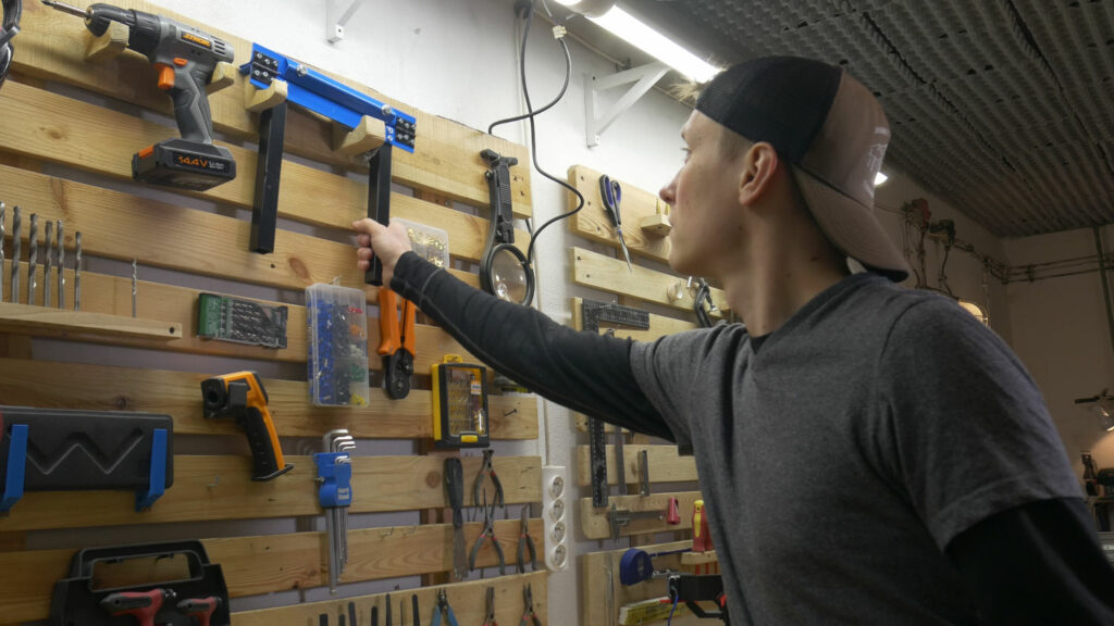
The small size makes it easy to store for example on your tool wall. Attaches quickly to the vice and hopefully will be often used in future projects. Machining aluminum with DIY CNC is cool but combined with a metal brake it literally adds another dimension to your parts.
Thanks for reading through the whole project! I hope you liked it and that maybe one-day MiniMetalBrake will show up in your workshop too! I am thinking about redesigning the machine to laser cut the parts out of thicker steel and improve some of its weak points and offer a kit for it in my store. Are you interested? Send me an email: nikodem@indystry.cc