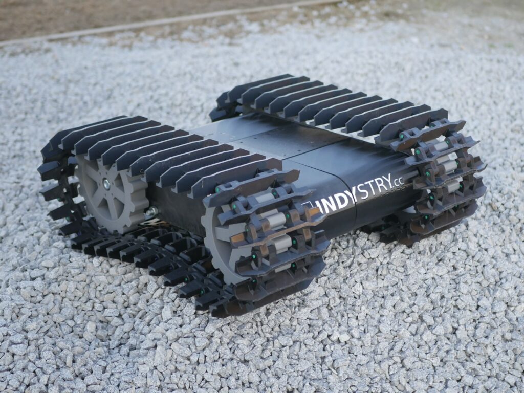
Big 3D printed robot platform on tracks
While working with GPS RTK and setting up my own RTK base station I thought it would be cool to […]
Big 3D printed robot platform on tracks Read Post »
While working with GPS RTK and setting up my own RTK base station I thought it would be cool to […]
Big 3D printed robot platform on tracks Read Post »
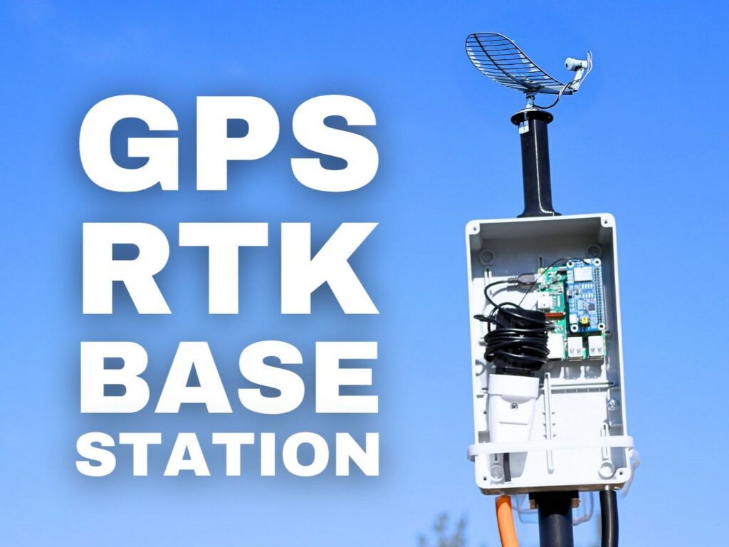
RTK is a cool technology but it’s also very expensive. As always with time as the adoption of the technology is growing the prices go lower and lower. The same happened with GPS RTK, these days (in 2025) you can buy LC29H from WasveShare for just $60…
How to use LC29H – the cheapest GPS RTK module Read Post »
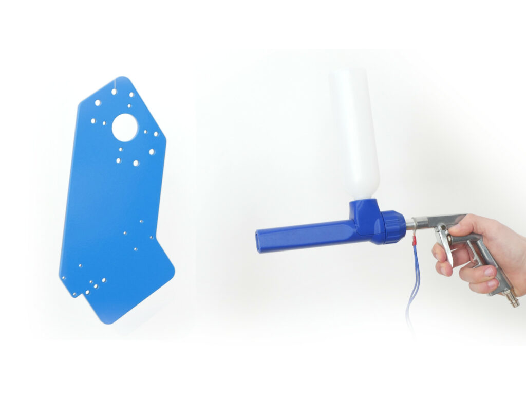
This will be a brief introduction to DIY powder coating. I would like to present you all the tools you
How to: DIY powder coating Read Post »
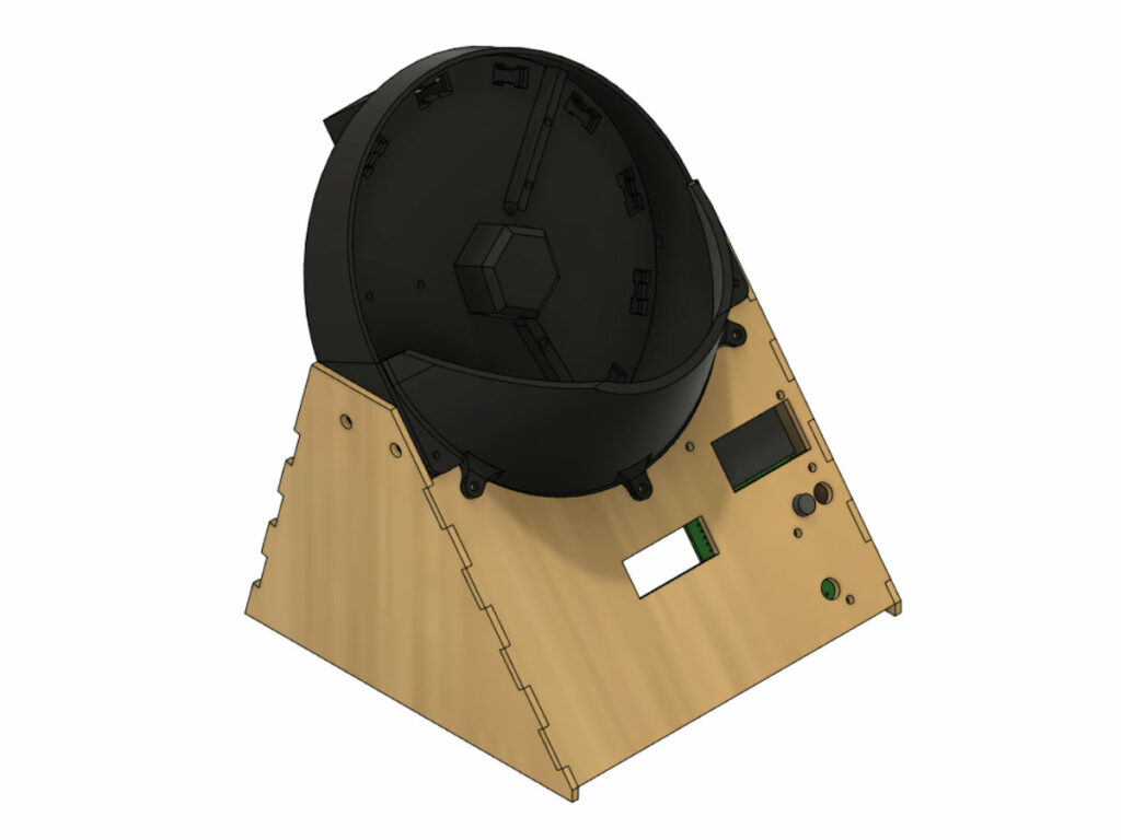
Since I started offering the parts to build an IndyMill I have been looking at various ways to optimize the
Screw Counting Machine Read Post »
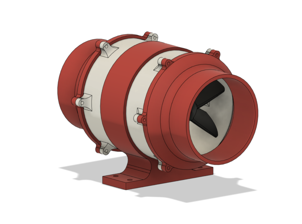
This is a 3D printed duct fan that can be used with a 775 motor or a popular BLDC (for
3D Printed duct fan Read Post »
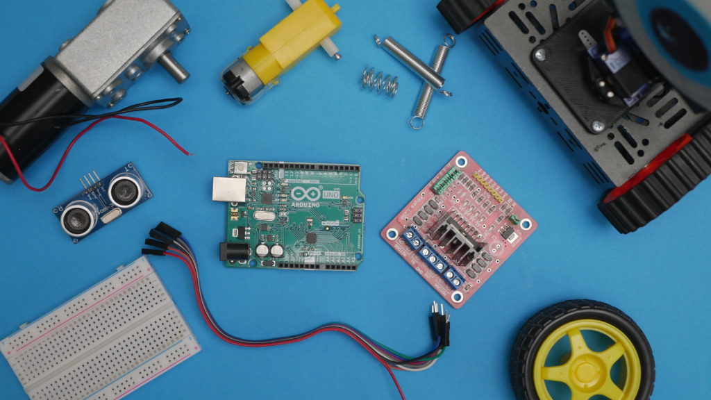
Robots are cool, I think we all agree on that. Right here I would like to give you a short
How to build a robot? Read Post »
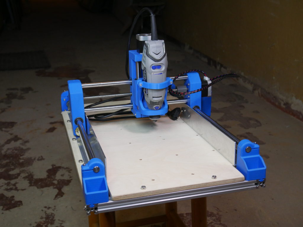
Dremel CNC – an easy-to-build low-cost 3D printed CNC machine that you can make on your own! It costs around
How to build 3D printed Dremel CNC? Read Post »