Since I started offering the parts to build an IndyMill I have been looking at various ways to optimize the process of preparing, packing, and branding. I think some of the things I am doing might be interesting for some of you as I am always trying to find the most DIY, easy and eco-friendly solutions. I will share more details about different methods and projects I created at Indystry.cc but in this project, I would like to focus on the most time-consuming problem – counting the screws.
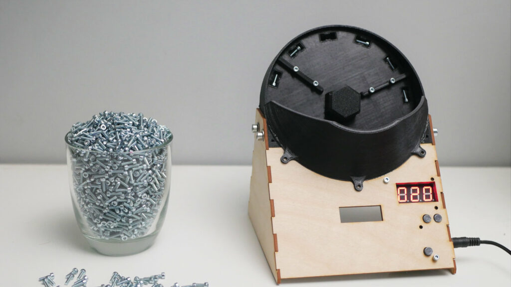
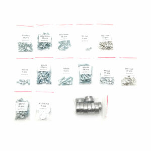
To illustrate how big of a problem that was let me tell you more about the set of screws for IndyMill. There are 13 different types of screws and nuts, in total 255 screws. So far every single screw had to be manually counted. I took great care when packing the screws and usually double-counted everything to make sure that each set was perfect.
-
 IndyMill Steel Plates Kit$189,00
 -
 IndyMill Screws & Bearings$59,00
 -
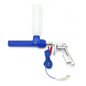 Powder Coating Gun$109,00
There are also bearings in the kit, only 10 of them so that’s easy to count. It takes about 8 hours to create 20 sets with all the components, considering I am not selling the parts at a huge volume it wasn’t a big problem but still there is plenty of room for improvement. The goal for this project was easy – building a machine that is able to easily, quickly, and accurately count screws.
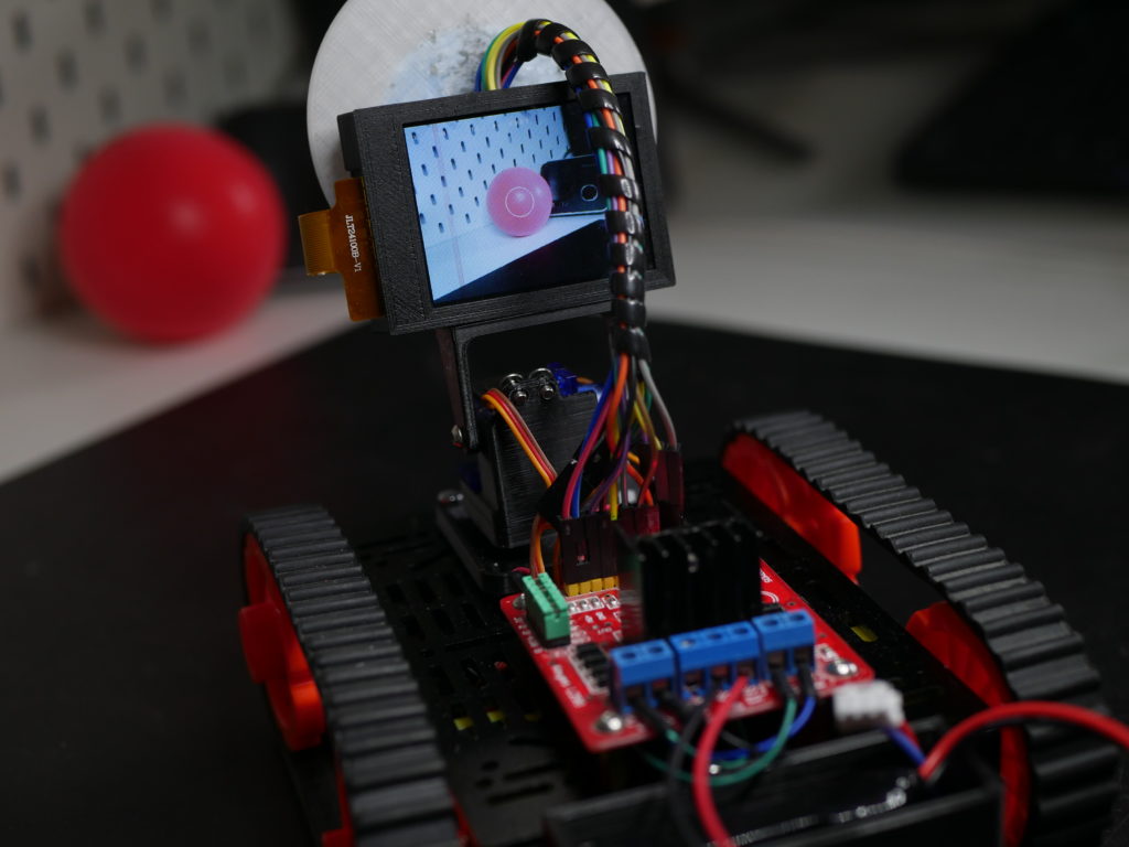
While the goal was pretty well defined getting all 3 subgoals at once is not easy at all and most likely will take at least a few iterations. For that reason from the beginning, I decided to treat this project as a prototype that lets me verify the idea and its feasibility. To test the idea and build a prototype we usually don’t need a lot and for that reason, I used cheap components, 3D printed parts, and thin plywood.
Design
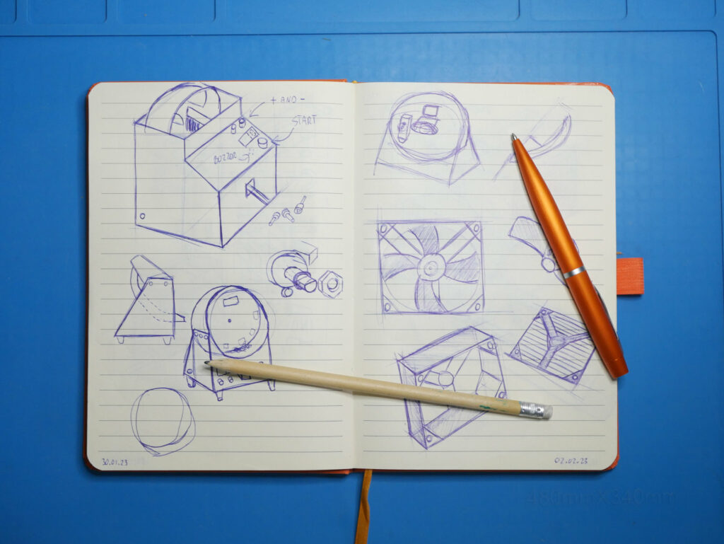
Design
Parts and files
You can find all the files required to build this project on my GitHub:

OpenScrewCounter
GitHub repository for open-source machine for precise and reliable screw counting. Designed with 3D printed and laser cut parts as well as Pi Pico based electronics.
And here is a list of parts I used for this project with links to some of them. Keep in mind that as I mentioned this is a prototype of a new machine I would like to build in the future. There are a lot of things that could be upgraded to make the machine more reliable and in general better.
| Name | Amount | Link |
| Raspberry Pi Pico | 1 | https://amzn.to/3FnSxVT |
| DC motor | 1 | https://amzn.to/405kJVr |
| 7 segment display | 1 | https://bit.ly/40bwYQB |
| Buttons | 3 | https://amzn.to/3yK9nul |
| 6804 Bearing | 1 | https://amzn.to/40ppZDR |
| Some screws | a lot | https://amzn.to/3leCWBm |
This is not a complete list of parts as there are a lot of small electronic components and also most likely you will have to adapt the project to your needs.
Manufacturing
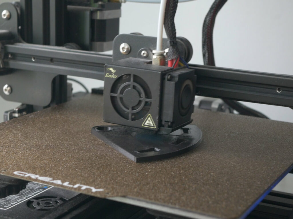
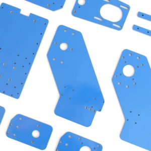
There are some 3D-printed parts you have to print on your own. It really doesn’t matter that much whether you use PLA or PETG, any material will do. Personally, I used PLA for this project. There are also plywood parts that I cut with a CO2 laser. Those parts can be easily replaced with 3D printed parts in case you don’t have an access to a laser cutter. Another alternative is to machine them with a CNC machine.
For printing, I used my slightly modified Ender3 printer. When I think about it now, this printer is already 4 years old and the only thing I replaced is the motherboard (I wanted to have silent TMC drivers, the original was perfectly fine and there was no reason to replace it), build plate (I broke the original one and adhesion on this golden powder plate is better) and plenty of nozzles. Everything else is as it originally was on the ender.
As a laser, I used my Epilog Zing 16. It is a really cool, professional and unfortunately pricey laser cutter. This cutter is a prize I won during one of the contests organized by Instructables, you should check them out! A cheaper alternative that require some upgrades out of the box to turn it into a usable and capable laser is a K40 laser like this one.
All the files are in the GitHub repository linked above.
Assembly
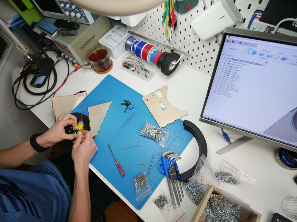
Assembly is so straightforward that I am not going to explain it in detail there. You need some M3 and M5 screws, wood glue might be useful to join plywood parts. In my video you can see some clips from the assembly but keep in mind I assembled the machine at 5 different stages of the design there and the final one differs a bit.
Problems
Instead of listing the problems let’s focus on the solutions:
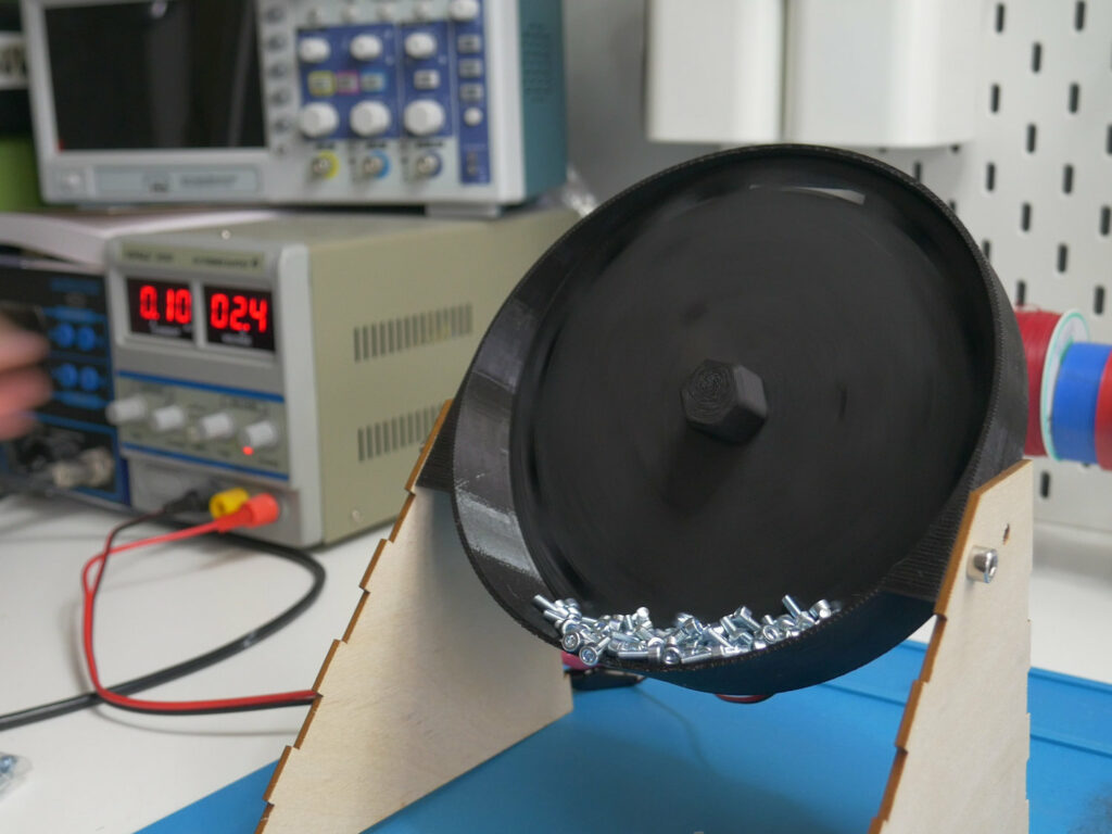
- Bigger drum – this is the element that holds the screws. It’s not big enough to hold a lot of screws. For my use case, it’s just a bit slow but I could easily use it as it is. But because I always want my projects to be appealing to a large audience I know a bigger drum may be beneficial.
- Better motor with an encoder – I used a very cheap motor, like a very very cheap motor, you can buy it for about a dollar. The next version should incorporate a more powerful motor capable of turning at slower and higher speeds depending on the need. Additionally, an encoder shall be used to allow for stall detection.
- More accurate laser sensor – using an LED and a photoresist is a decent solution but not accurate enough. Implementing two of these sensors to really make sure that the screws are properly counted is also to be considered.
- Bigger display with button/encoder – to control all the settings
- External communication interface – SPI, I2C or CAN to integrate the machine with other machines. For example a rotary table with containers of screws to allow for continuous counting.
I am pretty sure there is a lot more to upgrade, if you have any ideas and want to share them, feel free to send me an email.
Electronics, breadboard, CNC machining a PCB
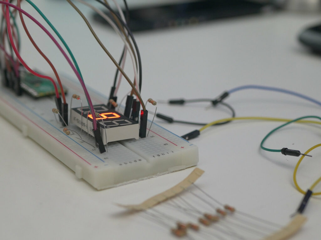
Starting with a breadboard prototype where modifying anything is really easy is always a good idea. So I started by connecting Pi Pico with 7 segment display to check if everything work as intended. The simple circuit assembled on the breadboard is presented in the image below.
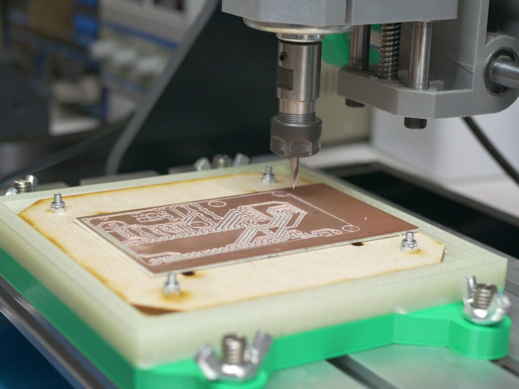
And after that, I moved to KiCAD to design the schematic and PCB layout. My plan was to make the PCB on my own with a modified CNC machine that I made just for PCB machining. And the result of that process you can see on the image above as well as in the video. PCB files are available in the GitHub repository as well.
Programming
Pi Pico or RP2040 can be programmed in Python and since I tried using this microcontroller I completely fell in love with it. Python is definitely my favorite programming language and as I am studying data science now for my master’s degree I am using it quite often for university projects.
The fun part while programming was using ChatGPT to write a function for controlling the 7-segment display. It wasn’t perfect it wasn’t working straight from the chat but the errors were easy to spot and fix. So definitely using this cool AI technology saved me some time for this project.
Other than that firmware for the project is rather simple. You can upload it to the pico with Thonny a simple IDE.
Final thoughts
Honestly, unfortunately, it’s not yet “production ready” I am not going to use it to pack the screws as I can’t trust it. The counting process is not reliable enough. I can use it as a machine that assists me during counting but to be 100% sure I have to count it manually too. So what’s next? Second better, bigger and more expensive version. Not a prototype but a production-ready unit. Follow my YouTube channel and Instagram to be notified when the project is ready, you can also support my work on Patreon: